An oblique non-contact three-dimensional linear velocity and dual-axis dynamic angle measurement system and method

A non-contact, angle measurement technology, applied in the direction of velocity/acceleration/shock measurement, velocity/acceleration/shock measurement equipment testing/calibration, measurement device, etc. The effect of good stability and high precision non-contact dual-axis dynamic angle measurement

Active Publication Date: 2022-04-08
ZHEJIANG UNIV +1
View PDF4 Cites 0 Cited by
  • Summary
  • Abstract
  • Description
  • Claims
  • Application Information

AI Technical Summary

Problems solved by technology

[0006] In order to solve the defects of low sensitivity and precision of the non-contact angle measurement method in the prior art, the present invention provides an oblique non-contact three-dimensional linear velocity and dual-axis dynamic angle measurement system and method, using two sets of three-dimensional The linear velocity measurement unit realizes the dual-axis dynamic angle measurement of the object. Each group of three-dimensional linear velocity measurement unit contains three laser vibrometers and an adjustment component that can adjust the angle of the outgoing light. Through the adjustment component, the three measuring laser beams are obliquely Focusing on a certain position on the surface of the dual-axis inertial measurement combination to be measured, there are three orthogonal motions in the dual-axis inertial measurement combination to be measured, forming the corresponding motion coordinates, which can solve the three-dimensional velocity information of the object in the motion coordinate system, because the two A group of laser vibrometers are respectively focused on two different positions of the dual-axis inertial measurement combination to be measured, so the corresponding dual-axis angle information in the moving coordinate system of the dual-axis inertial measurement combination to be measured can be solved

Method used


Image

  • An oblique non-contact three-dimensional linear velocity and dual-axis dynamic angle measurement system and method
  • An oblique non-contact three-dimensional linear velocity and dual-axis dynamic angle measurement system and method
  • An oblique non-contact three-dimensional linear velocity and dual-axis dynamic angle measurement system and method

Examples


Embodiment Construction

[0028] In order to better illustrate the purpose and advantages of the present invention, the content of the invention will be further described below in conjunction with the accompanying drawings and examples.

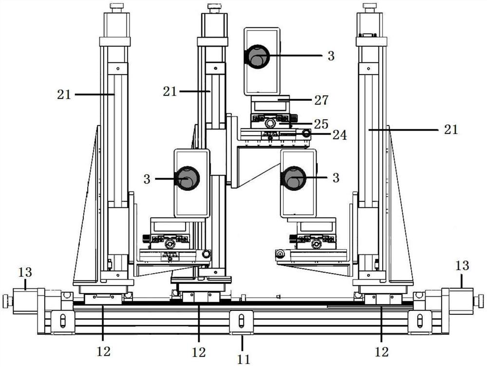
[0029] An oblique non-contact three-dimensional linear velocity and dual-axis dynamic angle measurement system, comprising a horizontal vibration isolation platform 4, a vibration table 5, a dual-axis inertial measurement combination 6 to be measured, and two sets of the above-mentioned three-dimensional linear velocity measurement units; The vibration table 5 described above is fixed at the center of the horizontal vibration isolation platform, the dual-axis inertial measurement unit 6 to be measured is installed on the vibration table 5, and two sets of three-dimensional linear velocity measurement units are installed on one side of the vibration table 5 respectively.

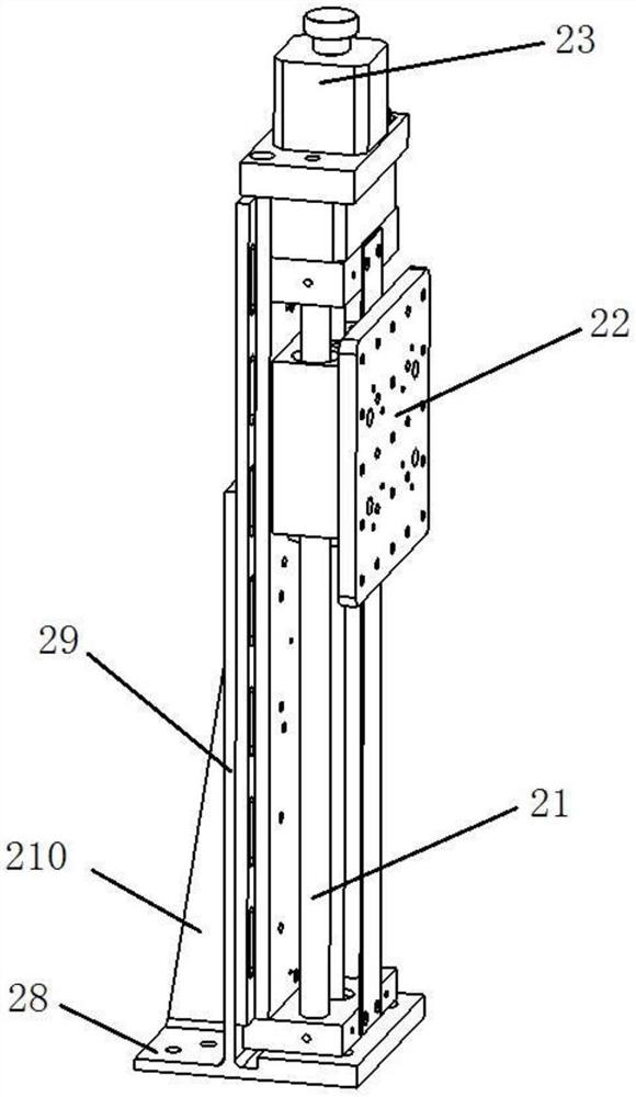
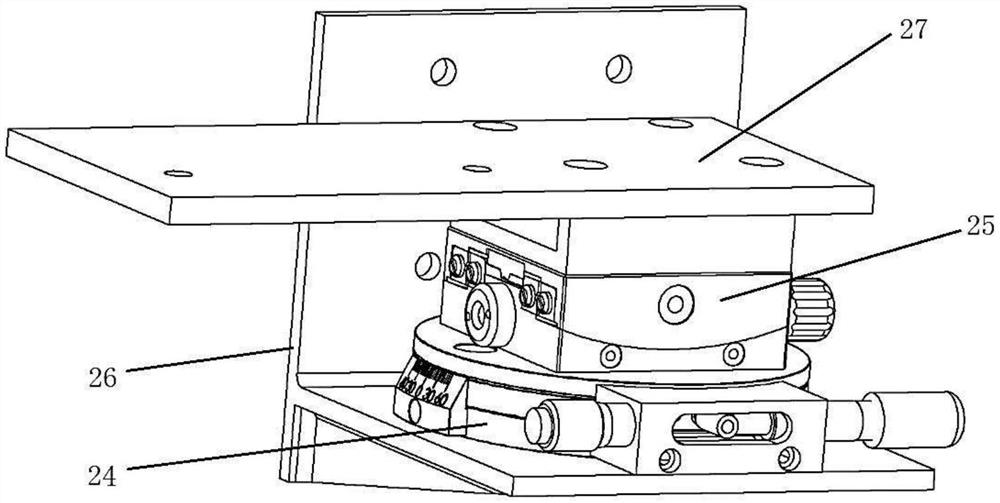
[0030] Such as figure 1 As shown, the three-dimensional linear velocity measurement unit adopted ...


PUM


Abstract

The invention discloses an oblique non-contact three-dimensional linear velocity and two-axis dynamic angle measurement system and method. The device includes a three-slider horizontal displacement platform, three sets of vertical displacement platforms and three laser vibrometers. Each set of vertical displacement platforms is equipped with a laser vibrometer. Through two sets of three-dimensional linear velocity measurement units, the object can be moved Two-axis dynamic angle measurement. Adjust the two sets of laser vibrometers to focus on two different positions of the two-axis inertial measurement combination to be tested. There are three orthogonal movements in the two-axis inertial measurement combination to be tested, forming corresponding motion coordinates, which can be solved to calculate the object in the motion coordinate system According to the three-dimensional velocity information in , the corresponding rotational angular velocity information can be calculated separately through the different positions of the selected points to be measured, and then integrated to obtain the angle information. The invention can be used in occasions such as inertial navigation device performance calibration, indexing mechanism calibration, etc., and has relatively broad application prospects in the fields of aerospace, navigation and positioning, and the like.

Description

technical field [0001] The invention relates to the field of optical sensing and measurement, in particular to an oblique non-contact three-dimensional linear velocity and dual-axis dynamic angle measurement system and method. [0002] technical background [0003] Due to the advantages of low cost and small size, the dual-axis inertial measurement combination is very popular in the fields of photoelectric stabilization systems, flying chess control systems, and intelligent driving. In the development process of the inertial measurement combination, it is often necessary to calibrate the dynamic angle error of the inertial instrument by using testing equipment such as a linear vibration table and an angular vibration table. However, the traditional method cannot separate the error of the instrument from the error of the test equipment, so it is impossible to accurately evaluate the dynamic angle error. Angle error, which in turn affects navigation performance. Therefore, the...

Claims


Application Information

Patent Timeline
Patent Type & Authority Patents(China)
IPC IPC(8): G01C19/72G01P3/36G01B11/00G01C25/00G01P21/02
CPCG01C19/728G01P3/36G01B11/002G01C25/005G01P21/02
Inventor 张登伟赵帅周一览管宁陈侃
Owner ZHEJIANG UNIV
Why Eureka
Try Eureka