Relay protection test wire box

A relay protection and test line technology, applied in the measurement of electrical variables, components of electrical measuring instruments, measuring devices, etc., can solve the problems of time-consuming and laborious, easy confusion, and scattered storage of short-circuit wires.

Pending Publication Date: 2020-10-23
STATE GRID JIANGSU ELECTRIC POWER CO LIANYUNGANG POWER SUPPLY CO +1
View PDF0 Cites 3 Cited by
  • Summary
  • Abstract
  • Description
  • Claims
  • Application Information

AI Technical Summary

Problems solved by technology

[0003] 1. Manual winding is required during recycling, which is time-consuming and laborious, and the scattered storage of short wires of different specifications is easy to confuse;
[0004] 2. There is a phenomenon that the wire itself or other short wires are knotted during use, and it is very cumbersome to sort out;
[0005] 3. Since the length of the wire is fixed and not stretchable, and the length of each specification wire is different, it is very easy to cause problems during use. Some wires are too long to affect the work of other staff, or the length of the prepared wire is too short to realize the calibration of the instrument. connection to the device being verified;
[0006] 4. After the calibration instrument is connected to the equipment to be calibrated, the line is overhead and not fixed, and other staff are prone to mistakenly touch and drag the line when passing by

Method used


Image

  • Relay protection test wire box
  • Relay protection test wire box
  • Relay protection test wire box

Examples


Embodiment Construction

[0020] The present invention will be further described below with reference to the accompanying drawings and specific embodiments.

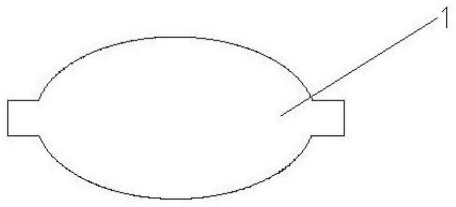
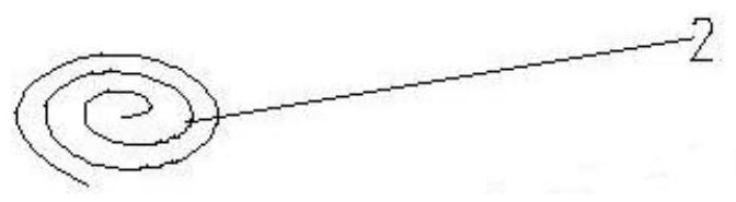
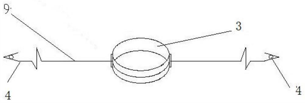
[0021] like Figure 1-4 As shown, the relay protection test wire box of the present invention includes a plurality of test wire automatic recovery boxes 16, and each test wire automatic recovery box 16 includes: upper covers 1, 2, wire pulleys 3, wire ends 4, wire outlet 5, A fixed column 6, a lower cover 7, a circular guide groove 8, and a wire 9, each end of the wire 9 is connected with a wire head 4, the inner sides of the upper cover 1 and the lower cover 7 are provided with a circular guide groove 8, and the lower cover is provided with a circular guide groove 8. The center of the circular guide groove 8 of 7 is provided with a fixed column 6 that is vertically and fixedly connected to the lower cover. And the circular guide groove 8 of the lower cover 7 only has the freedom of rotation, the mainspring 2 is arranged inside the wire wheel 3,...


PUM


Abstract

The invention discloses a relay protection test wire box which comprises a plurality of test wire automatic recovery boxes. The two ends of a wire are each connected with a thread; Circular guide grooves are formed in the inner sides of an upper cover and a lower cover; a fixing column vertically and fixedly connected with the lower cover is arranged at the circle center of the circular guide groove of the lower cover; a wire wheel is in a hollow cylinder shape and is arranged between the upper cover and the lower cover, and the wire wheel is limited by the circular guide grooves of the uppercover and the lower cover and only has a rotational degree of freedom; a clockwork spring is arranged in the wire wheel, the central end of the clockwork spring is fixed to the fixing column, and thetail end of the clockwork spring is fixedly connected with the inner surface of the wire wheel; the wire is folded in half at the center, the center point of the wire is fixedly connected with the outer surface of the wire wheel, the two sides of the folded wire are wound in parallel in the same direction along the outer surface of the wire wheel; and each test wire automatic recovery box is provided with two wire outlets, and the threads at the two ends of the wire penetrate out of the two wire outlets. Each phase of the test wire can be independently pulled out and withdrawn, manual windingis not needed in the withdrawing process, and the operation is simple and rapid.

Description

technical field [0001] The invention relates to a relay protection test junction box, which belongs to the technical field of electric power test equipment. Background technique [0002] In the calibration of relay protection equipment, test leads are needed to connect the calibration instrument and the secondary circuit or photoelectric circuit of the device to be calibrated to transmit voltage, current signals or position signals. These test wires are directly composed of copper wires (or optical fibers) with insulation. Each of these test wires is independently distributed and has different lengths. After use, it needs to be manually wound and sorted out, but there are many Messy wire storage without a fixed device. Because the test wires used in the relay protection are independently distributed, the lengths are different, and the following phenomena are easily caused: [0003] 1. Manual winding is required during recycling, which is time-consuming and labor-intensive,...

Claims


Application Information

Patent Timeline
Patent Type & Authority Applications(China)
IPC IPC(8): G01R1/04
CPCG01R1/0416
Inventor 王申树姜山苏登高张福来王飞亚王运霞李志华李昱瑾
Owner STATE GRID JIANGSU ELECTRIC POWER CO LIANYUNGANG POWER SUPPLY CO
Why Eureka
Try Eureka