Eureka AIR delivers breakthrough ideas for toughest innovation challenges, trusted by R&D personnel around the world.

Asymmetric multichannel radio frequency switch matrix device

A technology of radio frequency switch matrix and radio frequency switch, which is applied in the direction of electronic switches, electrical components, pulse technology, etc., and can solve the problem of a large number of PCB layers

Pending Publication Date: 2020-10-23
武汉博畅通信设备有限责任公司
View PDF0 Cites 0 Cited by
  • Summary
  • Abstract
  • Description
  • Claims
  • Application Information

AI Technical Summary

Problems solved by technology

[0004] In view of this, the present invention proposes an asymmetric multi-channel radio frequency switch matrix device to solve the problem of the number of PCB layers and the number of boards required by the traditional symmetrical multi-channel radio frequency switch matrix

Method used


Image

  • Asymmetric multichannel radio frequency switch matrix device
  • Asymmetric multichannel radio frequency switch matrix device
  • Asymmetric multichannel radio frequency switch matrix device

Examples


Embodiment Construction

[0026] The following will clearly and completely describe the technical solutions in the embodiments of the present invention in conjunction with the embodiments of the present invention. Obviously, the described embodiments are only part of the embodiments of the present invention, not all of them. Based on the implementation manners in the present invention, all other implementation manners obtained by persons of ordinary skill in the art without making creative efforts belong to the scope of protection of the present invention.

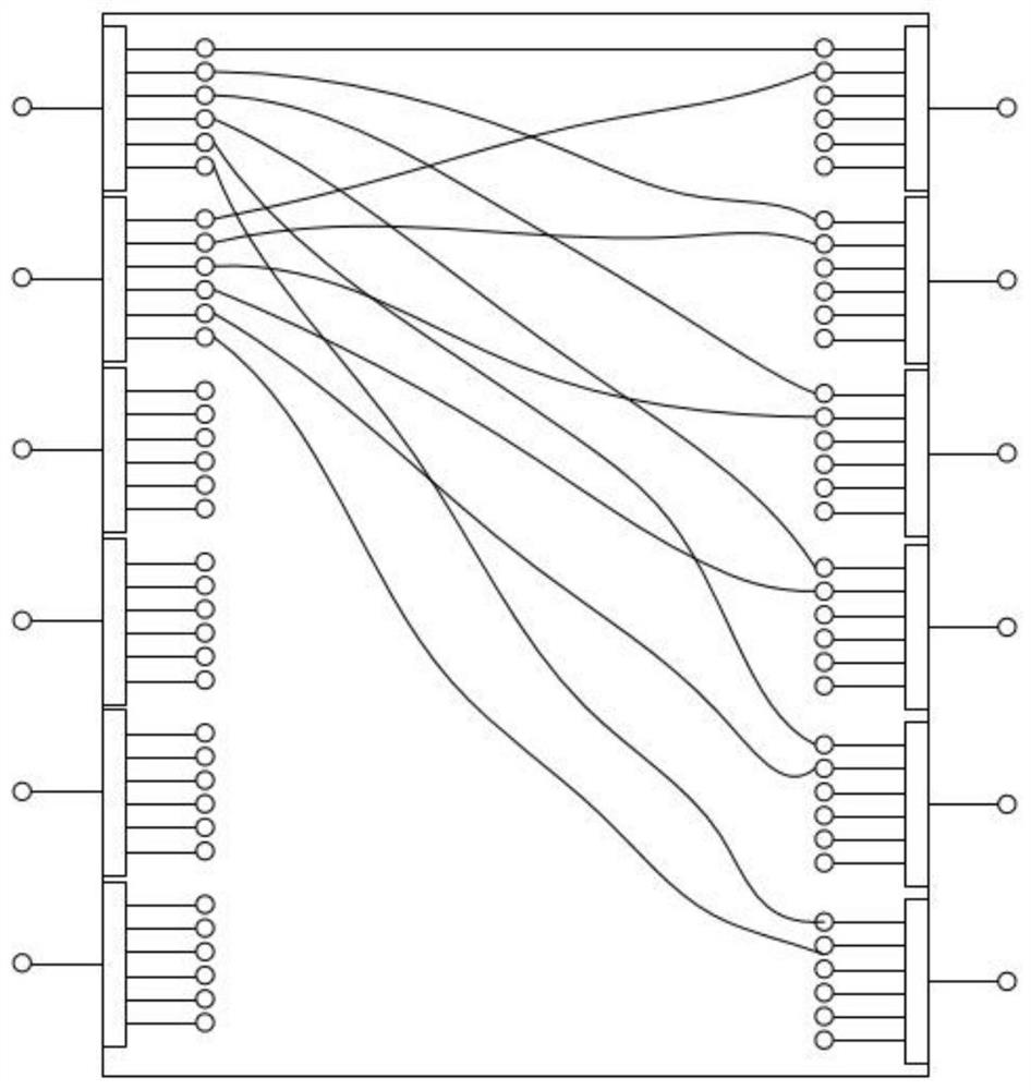
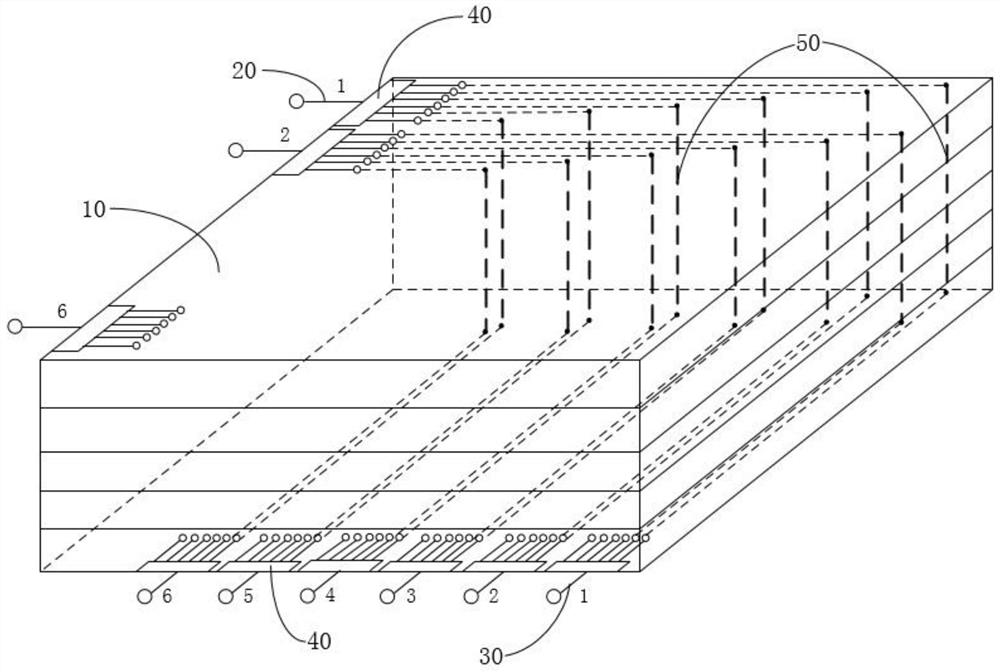
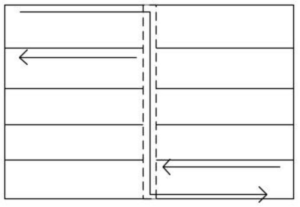
[0027] Such as figure 2 As shown, the asymmetric multi-channel radio frequency switch matrix device of the present embodiment includes a PCB board 10, a controller (not shown), N radio frequency signal input terminals 20, N radio frequency signal output terminals 30 and 2N radio frequency switches 40 ,Such as Figure 4 As shown, the PCB 10 includes a surface signal layer and a bottom signal layer, and the controller is connected to 2N radio frequ...


PUM


Abstract

The invention provides an asymmetric multichannel radio frequency switch matrix device. The device comprises a PCB, a controller, N radio-frequency signal input ends, N radio-frequency signal output ends and 2N radio-frequency switches, the PCB comprises a surface signal layer and a bottom signal layer, the controller is connected with the 2N radio-frequency switches, and each radio-frequency switch is provided with N signal channels. According to the asymmetric multichannel radio frequency switch matrix device, the radio frequency signal input end and the radio frequency signal output end arearranged perpendicular to each other, so that the input signal line and the output signal line are also perpendicular to each other, the radio frequency wiring does not intersect on the surface signal layer and the bottom signal layer, the requirement for the number of layers of the PCB is low, and the size and cost of the multichannel radio frequency switch matrix are reduced.

Description

technical field [0001] The invention relates to the technical field of radio frequency switch matrix, in particular to an asymmetric multi-channel radio frequency switch matrix device. Background technique [0002] Switch matrices are often used in automatic test equipment for various electronic equipment such as radar, communication, electronic countermeasures, identification friend or foe, and precision guidance. Switch matrices can quickly switch signal flows and are an indispensable part of channel switching in these systems. With the continuous improvement of the integration level of automated test equipment, the requirements for the switch matrix are getting higher and higher. First, the number of switch matrix channels is increasing, and second, the volume of the switch matrix is ​​getting smaller and smaller. [0003] At present, in the multi-channel switch matrix, the symmetrical structure of the input end and the output end is usually adopted, so that the PCB RF tr...

Claims


Application Information

Patent Timeline
IPC IPC(8): H03K17/00
CPCH03K17/002Y02D30/70
Inventor 付泉斌蔡楚才
Owner 武汉博畅通信设备有限责任公司
Why Eureka
Eureka Blog
Learn More