Supercharge Your Innovation With Domain-Expert AI Agents!

Punching die head connecting device convenient to replace

A technology of a connecting device and a stamping die, which is applied in the field of stamping and forming dies, can solve the problems of increasing the wear of the connecting part between the stamping head and the stamping machine, increasing the movable gap between the stamping head and the stamping machine, and reducing the movement accuracy of the stamping head, etc., so as to increase the work. Efficiency, increased concentricity, convenient and fast positioning effect

Inactive Publication Date: 2020-10-27
芜湖市夯福机械模具有限公司
View PDF6 Cites 0 Cited by
  • Summary
  • Abstract
  • Description
  • Claims
  • Application Information

AI Technical Summary

Problems solved by technology

[0004] In order to make up for the deficiencies of the prior art, the present invention proposes an easy-to-replace stamping die connecting device. Frequent impact and vibration during the process make the pins easy to wear due to vibration, and at the same time increase the movable gap between the punching head and the punching machine, increase the wear of the connecting part between the punching head and the punching machine, and reduce the movement accuracy of the punching head

Method used


Image

  • Punching die head connecting device convenient to replace
  • Punching die head connecting device convenient to replace
  • Punching die head connecting device convenient to replace

Examples


Embodiment approach

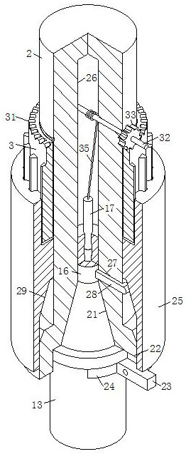
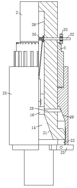
[0023] As an embodiment of the present invention, the bottom of the tapered groove 21 is provided with a No. 1 hole 26, and the top of the head 14 is provided with a round platform 16 that matches the No. 1 hole 26; the inner wall of the No. 1 hole 26 corresponds to the position of the round platform 16. A group of chute 27 is evenly distributed on the circumference, and a slider 28 is slidably connected to the chute 27. The end of the slider 28 away from the round platform 16 extends to the outside of the chute 27; part 29, the tapered part 29 is used to squeeze the slide block 28 after the casing 25 moves down, further increasing the connection stability between the punching head 13 and the punching machine; when the head 14 is embedded in the tapered groove 21, the head 14 drives the round table 16 to be inserted into the No. 1 hole 26, and then when the sleeve 25 rotates and locks the pressing rod 23, the tapered part 29 in the sleeve 25 rotates and moves downward, and then...


PUM


Abstract

The invention belongs to the technical field of punching forming dies, and particularly relates to a punching die head connecting device convenient to replace. The punching die head connecting devicecomprises a lower die, and the lower die is fixedly connected with a punching machine operation table. An upper die is arranged at the top of the lower die, and a puncher pin is in sliding connectionin a through hole formed in the middle of the upper die. A conic head is arranged at the top of the puncher pin, and a limiting ring is fixedly connected to the position, at the bottom of the head, ofthe puncher pin. A connecting rod fixedly connected with a punching machine drive part is arranged at the top of the puncher pin, and a conic groove cooperating with the head is formed at the bottomof the connecting rod. A set of grooves is evenly distributed on the circumference of the bottom of the connecting rod, press rods are arranged in the grooves, and the middles of the press rods are hinged to the side walls of the grooves through rotating pins. Arc clamping blocks are fixedly connected to the ends, close to the puncher pin, of the press rods, and after rotating, the press rods drive the clamping blocks to clamp the limiting ring. The lower end of the connecting rod is in threaded connection with a casing pipe, and the casing pipe is used for pressing down the press rods after rotating. The connecting stability of the puncher pin and the punching machine is increased in the manner that the casing pipe cooperates with the clamping blocks, and loosening and falling off are reduced.

Description

technical field [0001] The invention belongs to the technical field of stamping dies, in particular to an easily replaceable stamping die head connecting device. Background technique [0002] At present, stamping dies have become an indispensable tool for stamping factories. With the continuous development of stamping dies, stamping dies have been widely used due to their unique advantages, but some stamping dies still have certain problems, such as: complex structure, use It's cumbersome, doesn't keep workers safe, and isn't efficient [0003] In the prior art, there are also some technical solutions about the connecting device of the stamping die. For example, a Chinese patent with the application number of 2018207663269 discloses a stamping die replacement device, including an upper mold base and a lower mold base. The upper mold The bottom of the seat is fixedly provided with a punch fixing plate, and the punch fixing plate is provided with a punch and a stamping head, ...

Claims


Application Information

Patent Timeline
Patent Type & Authority Applications(China)
IPC IPC(8): B21D37/04B21D37/12
CPCB21D37/04B21D37/12
Inventor 陶老夯陶庭富
Owner 芜湖市夯福机械模具有限公司
Features
  • R&D
  • Intellectual Property
  • Life Sciences
  • Materials
  • Tech Scout
  • Unparalleled Data Quality
  • Higher Quality Content
  • 60% Fewer Hallucinations
Learn More