Metal sheet punching and folding composite forming machine

A composite forming, metal sheet technology, applied in the direction of metal processing equipment, feeding device, stripping device, etc., can solve the problems of errors, poor feeding and unloading stability, unusable and other problems

Pending Publication Date: 2020-10-27
赵梅
View PDF7 Cites 0 Cited by
  • Summary
  • Abstract
  • Description
  • Claims
  • Application Information

AI Technical Summary

Problems solved by technology

[0002] In order to meet the needs of use in life, it is often necessary to punch and compound metal sheets into the desired shape. Usually, it is necessary to process the metal sheet into a "U" or "C" shape for the construction of pipelines and the repair of various structures. , but the current metal sheet

Method used


Image

  • Metal sheet punching and folding composite forming machine
  • Metal sheet punching and folding composite forming machine
  • Metal sheet punching and folding composite forming machine

Examples


specific Embodiment approach 1

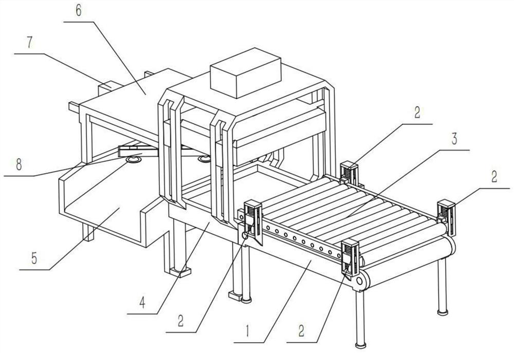
[0035] Combine below Figure 1-13 Describe this embodiment, a metal sheet punching and folding compound forming machine, a transmission mechanism 1 and a stamping mechanism 4, the metal sheet punching and folding compound forming machine also includes a pressing frame 2, an auxiliary mechanism 3, a row carriage 5, and a supporting mechanism 6 , pushing mechanism 7 and pick-up mechanism 8, described compression frame 2 is provided with four, and the outside of described transmission mechanism 1 upper end four corners places is all fixedly connected with compression frame 2, and described auxiliary mechanism 3 and four compression frames 2 fixed connection, the stamping mechanism 4 is fixedly connected to the rear end of the transmission mechanism 1, the row carriage 5 is fixedly connected to the rear end of the stamping mechanism 4, the support mechanism 6 is fixedly connected to the upper end of the row carriage 5, The pushing mechanism 7 is slidably connected to the top of th...

specific Embodiment approach 2

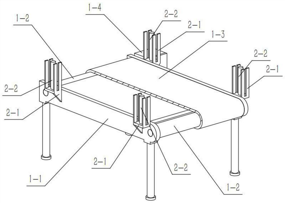
[0037] Combine below Figure 1-13 Illustrate this embodiment, and this embodiment will further illustrate Embodiment 1. The transmission mechanism 1 includes a transmission frame 1-1, a pulley 1-2, a conveyor belt 1-3 and a motor I1-4, and the pulley 1-2 Two pulleys 1-2 are provided, and the two pulleys 1-2 are respectively rotatably connected to the two sides of the upper end of the transmission frame 1-1, and the two pulleys 1-2 are connected through the transmission belt 1-3, and the motor I1-4 is fixedly connected to the The outer side of the rear part of the upper end of the transmission frame 1-1, and the output shaft of the motor I1-4 is fixedly connected to the rear side pulley 1-2, and the four pressing frames 2 are respectively fixedly connected to the four corners of the upper end of the transmission frame 1-1 The outer side of the stamping mechanism 4 is fixedly connected to the rear end of the transmission frame 1-1.

[0038] Start the motor Ⅰ1-4, the output shaf...

specific Embodiment approach 3

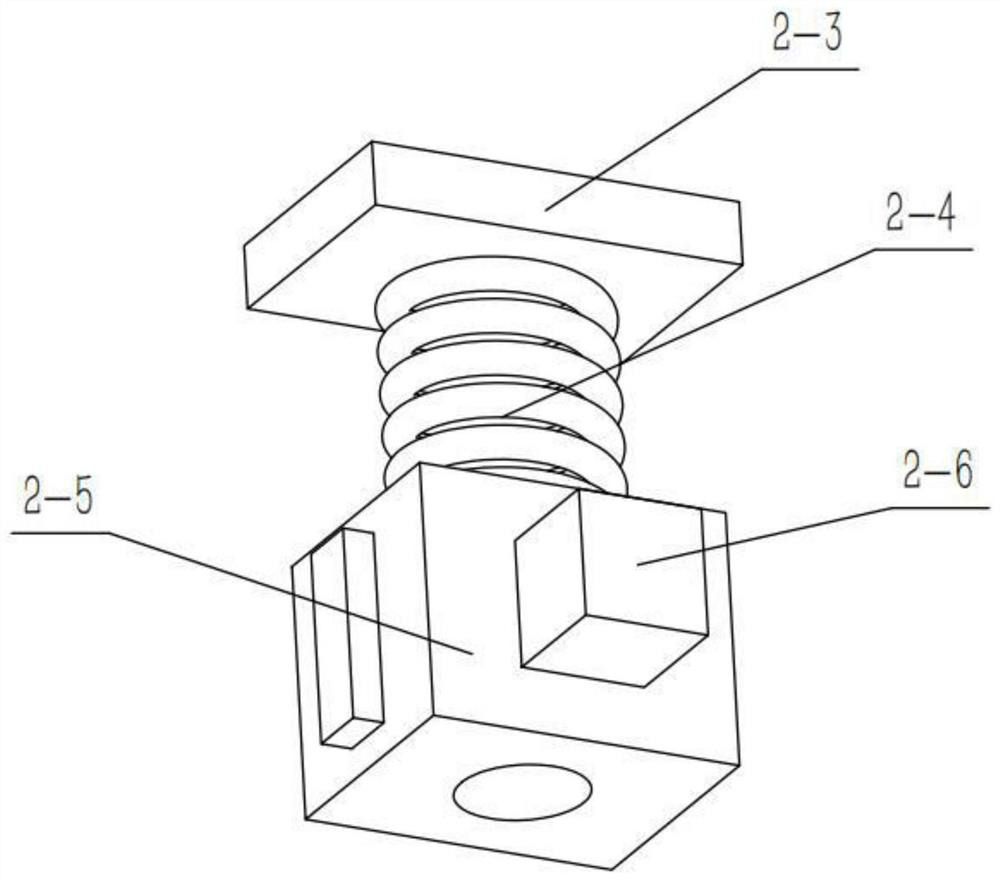
[0040] Combine below Figure 1-13 Describe this embodiment, this embodiment will further explain the second embodiment, the pressing frame 2 includes a sliding frame 2-1, a sliding rod 2-2, an end plate 2-3, a spring 2-4, a sliding block 2- 5 and a fixed block 2-6, the sliding rod 2-2 is fixedly connected to the inside of the sliding frame 2-1, the end plate 2-3 is fixedly connected to the upper end of the sliding frame 2-1, and the spring 2-4 fixedly connected to the lower end of the end plate 2-3, the sliding block 2-5 is fixedly connected to the lower end of the spring 2-4, and both the spring 2-4 and the sliding block 2-5 are slidably connected to the sliding rod 2-2, The inner side of the sliding block 2-5 is provided with a fixed block 2-6, and the four sliding frames 2-1 are respectively fixedly connected to the outer sides of the four corners of the upper end of the transmission frame 1-1, and the four fixed blocks 2-6 All are fixedly connected with the auxiliary mech...


PUM


Abstract

The invention relates to the technical field of metal sheet processing equipment, in particular to a metal sheet punching and folding composite forming machine. The metal sheet punching and folding composite forming machine comprises a conveying mechanism and a punching mechanism, and further comprises pressing frames, an auxiliary mechanism, a discharging sliding frame, a supporting mechanism, apushing mechanism and a picking mechanism, the number of the pressing frames is four, the outer sides of four corners of the upper end of the conveying mechanism are fixedly connected with the pressing frames, the auxiliary mechanism is fixedly connected with the four pressing frames, the punching mechanism is fixedly connected to the rear end of the conveying mechanism, the discharging sliding frame is fixedly connected to the rear end of the punching mechanism, the supporting mechanism is fixedly connected to the upper end of the discharging sliding frame, the pushing mechanism is slidably connected to the top end in the supporting mechanism, and the picking mechanism is fixedly connected to the lower end of the pushing mechanism. The metal sheet punching and folding composite forming machine can improve the supply stability and also improve the discharging stability, meanwhile, manual participation in feeding and discharging is avoided, and a clamping injury accident is avoided.

Description

technical field [0001] The invention relates to the technical field of metal sheet processing equipment, and more specifically relates to a metal sheet punching and folding compound forming machine. Background technique [0002] In order to meet the needs of use in life, it is often necessary to punch and fold metal sheets into the required shape. Usually, the metal sheet needs to be processed into a "U" shape or "C" shape, which is used in the construction of pipelines and the repair of various structures. , but the current metal sheet punching and folding compound forming machine has poor loading and unloading stability, and it is very easy to make mistakes in the punching position, resulting in unusability, and the process of loading and unloading often requires manual participation, which is extremely difficult. prone to pinch accidents. Contents of the invention [0003] The purpose of the present invention is to provide a sheet metal punching and folding compound fo...

Claims


Application Information

Patent Timeline
IPC IPC(8): B21D43/18B21D43/02B21D43/12B21D22/02B21D45/00
CPCB21D22/02B21D43/027B21D43/12B21D43/18B21D45/00
Inventor 赵梅
Owner 赵梅
Why Eureka
Try Eureka