Efficient mechanical maintenance prizing equipment

A mechanical and efficient technology, applied in the direction of workpiece clamping devices, manufacturing tools, etc., can solve the problems of mechanical prying influence, shaking, mechanical shedding, etc.

Inactive Publication Date: 2020-10-27
徐月美
View PDF1 Cites 0 Cited by
  • Summary
  • Abstract
  • Description
  • Claims
  • Application Information

AI Technical Summary

Problems solved by technology

A kind of high-efficiency mechanical maintenance skid-mounted equipment in the above-mentioned patent has the following disadvantages: when the machine is skid-mounted, the existing equipment cannot effectively fix the machine due to shaking during the skid-mounted process. It will cause the machinery to fall off from the equipment, which will affect the skid installation of the machinery

Method used


Image

  • Efficient mechanical maintenance prizing equipment
  • Efficient mechanical maintenance prizing equipment
  • Efficient mechanical maintenance prizing equipment

Examples


Embodiment 1

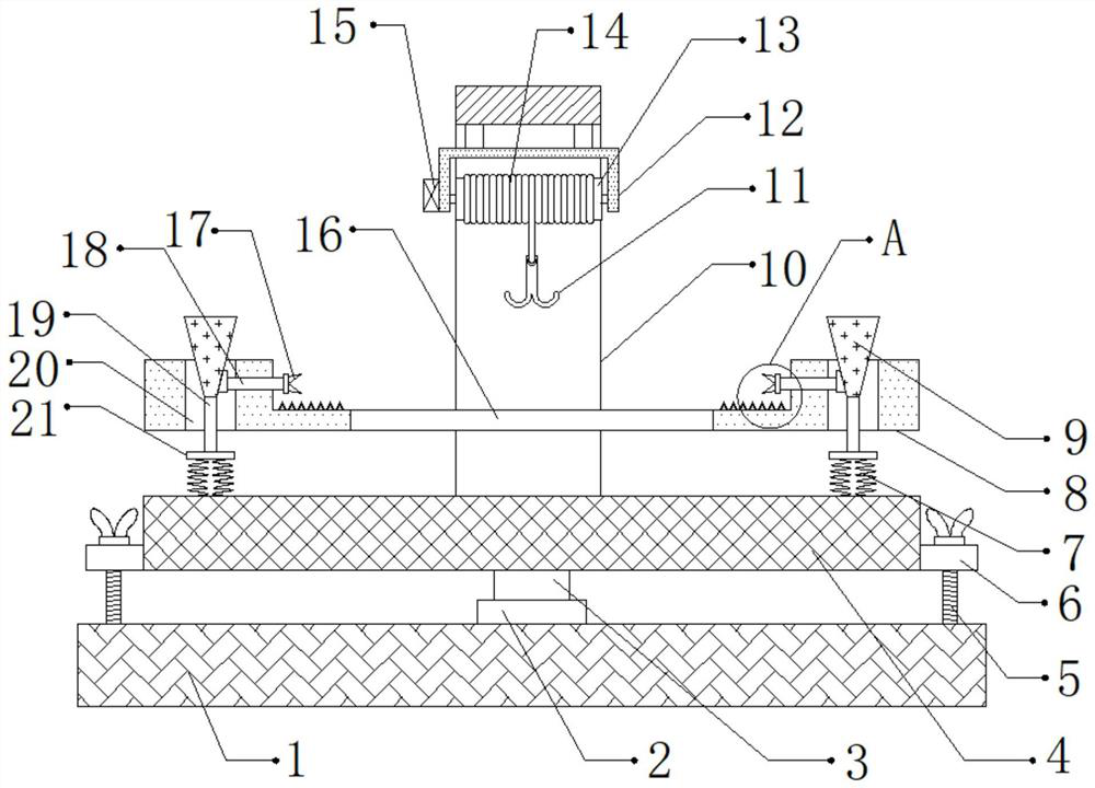
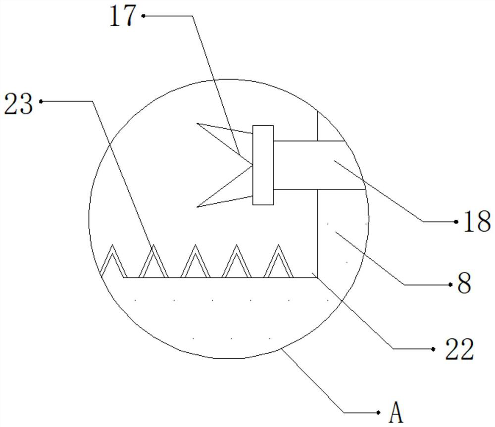
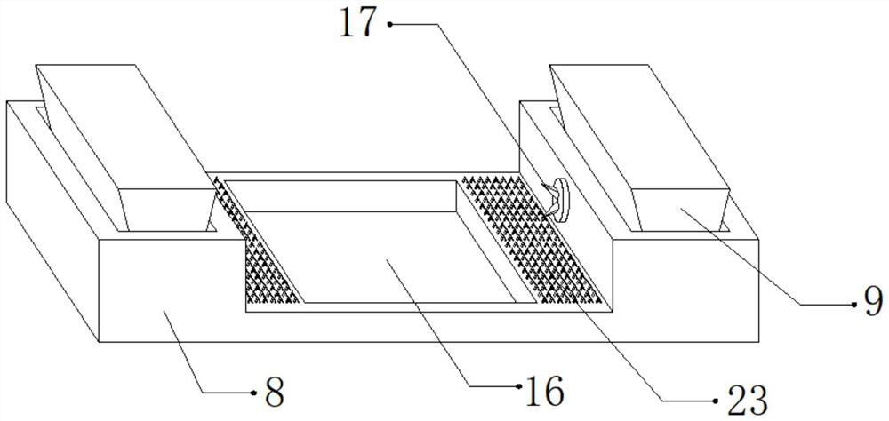
[0028] refer to Figure 1-3 , an efficient mechanical maintenance skid-mounted equipment, including a fixed seat 1 and a support plate 8, the top outer wall of the fixed seat 1 is connected with a damping bearing 2 through bolts, and the inner wall of the damping bearing 2 is rotatably connected with a rotating shaft 3, and the top outer wall of the rotating shaft 3 The fixing plate 4 is connected by bolts, and both sides of the top outer wall of the fixing plate 4 are connected with springs 7 by bolts. Rod 19, the top outer wall of the support rod 19 is connected with a connecting block 9 by bolts, and the cross section of the connecting block 9 is a trapezoid, and both sides of the top outer wall of the support plate 8 are provided with through holes 20, and the connecting block 9 is located in the through hole 20. Inside, one side of the inner wall of the two through holes 20 is provided with a socket, and the inner wall of the two sockets is inserted with a fixing rod 18, ...

Embodiment 2

[0038] refer to Figure 4 , a high-efficiency mechanical maintenance skid-mounted equipment. Compared with the first embodiment, the outer wall of one side of the fixing frame 10 is provided with a ventilation opening, and the inner wall of the ventilation opening is connected with a fan 24 by bolts, which can prevent the adhesion of mechanical The dust and debris on the machine are treated to prevent the dust and debris from adhering to the surface of the machine and causing interference to the maintenance of the machine.

[0039] Working principle: When in use, place the machinery that needs to be repaired and skid-mounted inside the U-shaped groove 22, preliminarily fix the machinery through the tooth block 17, start the motor 15, and the motor 15 will drive the hanging rope 14 and the hook 11 to carry out Move down to fix the top of the machine on the hook 11. After the fixing is completed, start the motor 15, and the motor 15 will drive the winding roller 13 to rotate, so...


PUM


Abstract

The invention discloses efficient mechanical maintenance prizing equipment which comprises a fixed seat and a supporting plate. A damping bearing is fixedly connected to the outer wall of the top of the fixed seat, a rotating shaft is rotatably connected to the inner wall of the damping bearing, a fixed plate is fixedly connected to the outer wall of the top of the rotating shaft, springs are fixedly connected to two sides of the outer wall of the top of the fixed plate, a supporting block is fixedly connected to the outer walls of the tops of the springs, a supporting rod is fixedly connectedto the outer wall of the top of the supporting block, a connecting block is fixedly connected to the outer wall of the top of the supporting rod, the cross section of the connecting block is trapezoidal and through holes are formed in two sides of the outer wall of the top of the supporting plate. The efficient mechanical maintenance prizing equipment can prevent a machine from falling from the equipment as a clamping force is relatively small, can prevent the machine from falling from the equipment due to gravity of the equipment, can dedust the bottom of the machine conveniently, and can rotate the machine so as to maintain and process other parts of the machine.

Description

technical field [0001] The invention relates to the technical field of mechanical maintenance, in particular to an efficient mechanical maintenance skid-mounted device. Background technique [0002] When repairing machinery, it is necessary to lift the machinery to facilitate the operation of maintenance personnel, while general machinery needs to use skid-mounted equipment during maintenance. [0003] After searching, the Chinese patent authorization number is CN209453515U, which discloses a high-efficiency mechanical maintenance skid-mounted equipment, including a base, a motor and a hydraulic cylinder, a motor is installed in the middle of the base, and fixed columns are provided on the left and right sides of the base , and the fixing column is connected with the ejector rod through the first spring, the ejector rod is connected with the support seat through the chute, and the support seat is provided with a fixing groove, and a support rod is installed in the fixing gro...

Claims


Application Information

Patent Timeline
Patent Type & Authority Applications(China)
IPC IPC(8): B25B11/00B25B11/02
CPCB25B11/00B25B11/02
Inventor 郑元态
Owner 徐月美
Why Eureka
Try Eureka