Graphite gasket equipment for slicing processing of graphite rod

A graphite pad, graphite rod technology, applied in stone processing equipment, stone processing tools, work accessories, etc., to achieve the effect of reducing errors, consistent thickness, and reducing labor intensity

Active Publication Date: 2020-10-27
山西博翔汇良新材料有限公司
View PDF9 Cites 3 Cited by
  • Summary
  • Abstract
  • Description
  • Claims
  • Application Information

AI Technical Summary

Problems solved by technology

[0005] In order to overcome the disadvantage that manual hand-held cutting equipment is needed to slice graphite rods, the technical problem to be solved by the present invention is to provide a graphite rod slicing graphite gasket processing equipment that can automatically slice graphite rods and evenly slice graphite rods

Method used


Image

  • Graphite gasket equipment for slicing processing of graphite rod
  • Graphite gasket equipment for slicing processing of graphite rod
  • Graphite gasket equipment for slicing processing of graphite rod

Examples


Embodiment 1

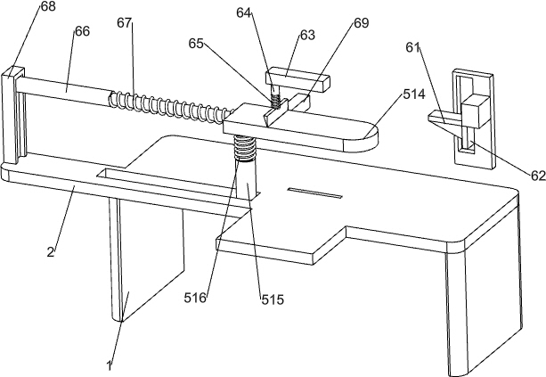
[0025] A graphite rod slice processing graphite gasket equipment, such as Figure 1-3 As shown, it includes a support plate 1, an operation plate 2, a storage plate 3, a mounting plate 4 and a cutting mechanism 5, the left and right sides of the bottom of the operation plate 2 are connected with the support plate 1, and the right side of the operation plate 2 rear side is connected with a The storage board 3 and the right side of the top of the operation board 2 are connected with an installation board 4 , and a cutting mechanism 5 is installed between the operation board 2 , the storage board 3 and the installation board 4 .

[0026] The cutting mechanism 5 includes an L-shaped connecting plate 51, a feeding pipe 52, a servo motor 53, a sprocket drive group 54, a slider 55, a first connecting plate 56, a second connecting plate 57, a first telescopic rod 58, a first Spring 59, inclined head block 510, limit slideway 511, the third connecting plate 512, blade 513, material ret...

Embodiment 2

[0029] On the basis of Example 1, such as figure 1 and Figure 4As shown, it also includes a stopper mechanism 6, and the stopper mechanism 6 includes a first wedge block 61, a baffle plate 62, a fourth connecting plate 63, a third telescopic rod 64, a third spring 65, a fourth telescopic rod 66, The fourth spring 67, slotted connecting plate 68 and the fifth connecting plate 69, the left side of the second connecting plate 57 is connected with the first wedge-shaped block 61, the right side of the first wedge-shaped block 61 is connected with the baffle plate 62, and the feeding pipe 52 The left side is connected with the fourth connecting plate 63, the left side of the fourth connecting plate 63 bottom is connected with the third telescopic rod 64, the telescopic end of the third telescopic rod 64 is connected with a push plate, and the push plate is connected with the third telescopic rod 64. The third spring 65 is arranged, and the top of the operation plate 2 on the left...

Embodiment 3

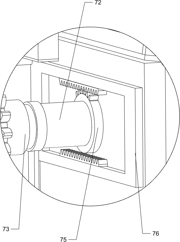
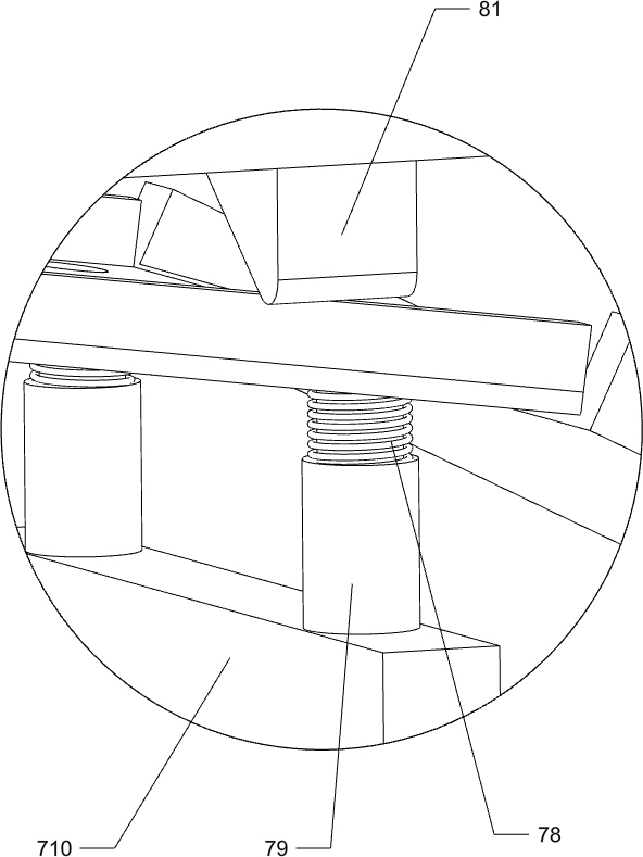
[0032] On the basis of Example 2, such as figure 1 and Figure 5-7 As shown, it also includes a dust removal mechanism 7, and the dust removal mechanism 7 includes a rack plate 71, a transmission rod 72, a one-way clutch 73, a transmission gear 74, a half gear 75, a rack frame 76, a screening frame 77, a fifth Spring 78, the fifth telescopic rod 79, the sixth connecting plate 710 and the seventh connecting plate 711, the bottom of the fifth connecting plate 69 is connected with a rack plate 71, and the operation plate 2 on the front side of the limit slideway 511 is rotatably connected with Transmission rod 72, the rear side of transmission rod 72 is connected with one-way clutch 73, is connected with transmission gear 74 on the one-way clutch 73, and transmission gear 74 meshes with rack plate 71, and transmission rod 72 front side is connected with half gear 75, and transmission rod 72 The top of the operation plate 2 on the front side is slidingly connected with the sevent...


PUM


Abstract

The invention relates to graphite rod processing equipment, in particular to graphite gasket equipment for slicing processing of a graphite rod. According to the graphite gasket equipment for slicingprocessing of the graphite rod, the graphite rod can be automatically and uniformly sliced. The graphite gasket equipment for slicing processing of the graphite rod comprises a working plate, an object placing plate, a mounting plate and a cutting mechanism, wherein supporting plates are both connected to the two sides of the bottom of the working plate; the object placing plate is connected to one side of the working plate; the mounting plate is connected to one side of the top of the working plate; and the cutting mechanism is arranged between the working plate, the object placing plate andthe mounting plate. According to the graphite gasket equipment, the graphite rod can be automatically and uniformly sliced through the cutting mechanism, the thicknesses of the slices are consistent,the error is reduced, the graphite rod is sliced without manually holding cutting equipment, the cut wound of the finger is prevented, and the labor intensity can be reduced.

Description

technical field [0001] The invention relates to graphite rod processing equipment, in particular to graphite rod slice processing graphite gasket equipment. Background technique [0002] At present, the slicing of graphite rods is generally done manually. When slicing manually, the cutting equipment is manually held, and then the cutting equipment is moved up and down to slice the graphite rods. When manually slicing, it is necessary to manually push the graphite rods. In this way, fingers are easily cut during the slicing process, and manual slicing is difficult to keep the thickness of the slices consistent, there are errors, and manual slicing is labor-intensive. [0003] Therefore, there is an urgent need to develop a graphite rod slicing processing graphite gasket equipment that can automatically slice graphite rods and evenly slice graphite rods. Contents of the invention [0004] (1) Technical problems to be solved [0005] In order to overcome the disadvantage th...

Claims


Application Information

Patent Timeline
Patent Type & Authority Applications(China)
IPC IPC(8): B28D1/22B28D7/00B28D7/02
CPCB28D1/22B28D7/00B28D7/02
Inventor 张少东
Owner 山西博翔汇良新材料有限公司
Why Eureka
Try Eureka