Cast-in-place box girder construction system and construction method for excavation section of existing in-service line modified bridge

A box girder construction and box girder technology, applied in bridges, bridge materials, bridge construction, etc., can solve the problems of long construction period, time-consuming and laborious, and large consumption of construction support formwork.

Pending Publication Date: 2020-10-27
ANHUI ROAD & BRIDGE GRP
View PDF0 Cites 7 Cited by
  • Summary
  • Abstract
  • Description
  • Claims
  • Application Information

AI Technical Summary

Problems solved by technology

[0004] The purpose of the present invention is to provide a cast-in-place box girder construction system and construction method in the excavation section of the existing existing line to the bridge, aiming to solve the problem of large consumption of formwork and long construction period in the erection and removal of the construction support in the widening operation of the existing existing road in active service , time-consuming technical problems

Method used


Image

  • Cast-in-place box girder construction system and construction method for excavation section of existing in-service line modified bridge
  • Cast-in-place box girder construction system and construction method for excavation section of existing in-service line modified bridge
  • Cast-in-place box girder construction system and construction method for excavation section of existing in-service line modified bridge

Examples


Embodiment Construction

[0047] In order to make the purpose, technical solutions and advantages of the embodiments of the present invention clearer, the technical solutions in the embodiments of the present invention will be clearly and completely described below in conjunction with the embodiments of the present invention. Obviously, the described embodiments are part of the present invention Examples, not all examples. Based on the embodiments of the present invention, all other embodiments obtained by persons of ordinary skill in the art without creative efforts fall within the protection scope of the present invention.

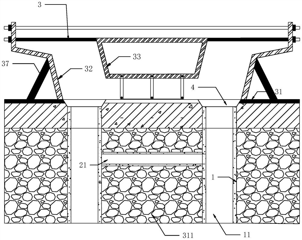
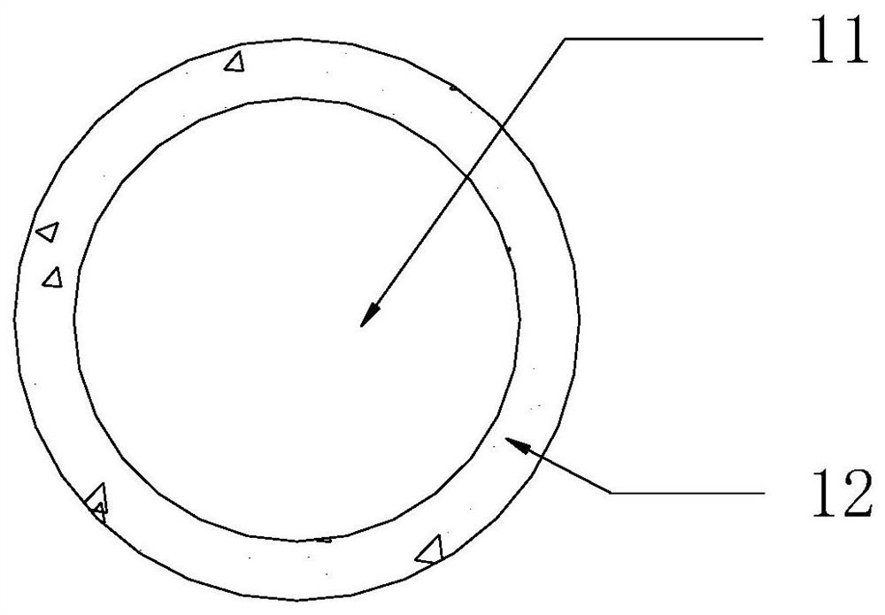
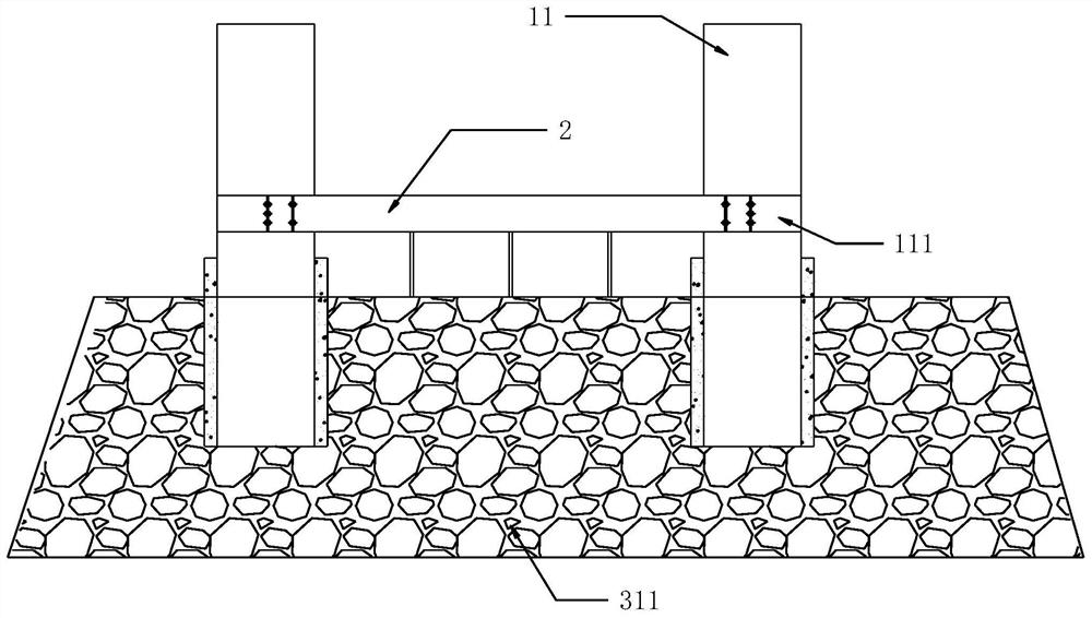
[0048] combined with Figure 1 to Figure 8 , the present invention provides a cast-in-situ box girder construction system and construction method in the excavation section of the existing existing road to the bridge, aiming to solve the time-consuming and labor-intensive technology of erecting the full hall support and removing the construction support formwork in the widening op...


PUM


Abstract

The invention provides a cast-in-place box girder construction system and construction method for an excavation section of an existing in-service line modified bridge. Stand columns of a stand columnpre-isolation structure are pre-buried in backfill soil of a foundation; a foam light soil pipe is positioned and sleeved on each stand column; tie beam side dies and tie beam bottom dies of a tie beam supporting structure are positioned on the outer side of a tie beam; the tie beam side dies are arranged between the stand columns, and two ends are respectively connected with the stand columns; the tie beam bottom dies are positioned and supported through low brackets and are used for realizing the positioning arrangement of tie beams; the lower portion of a box girder outer side die of a boxgirder formwork structure is located on a box girder bottom die through a supporting frame, and the upper portion is located through a pull rod assembly; and a box girder inner side die is positionedin the box girder outer side die. By arranging the stand column pre-isolation structure, the tie beam supporting structure and the box girder formwork structure, full framing and corresponding construction support formwork dismounting are not needed, more time and labor are saved, the construction period is greatly shortened, and the system is economical, practical and suitable for wide popularization.

Description

technical field [0001] The invention relates to the technical field of cast-in-place box girder construction of bridges, in particular to a cast-in-place box girder construction system and a construction method for an excavation section of a bridge from an existing line in active service. Background technique [0002] With the continuous development of China's economy, the infrastructure construction of major cities is also in progress. Almost every day there are new planned roads ready for construction. These new planned roads will inevitably intersect with many existing roads. At this time, we usually There will be two options, one is worn under and the other is worn over. When the planned road is an underpass road, we generally change the old road with intersections into a bridge. Due to the short construction period and limited construction site of this kind of underpass road project, cast-in-place box girders are generally used, and the construction technology is gener...

Claims


Application Information

Patent Timeline
Patent Type & Authority Applications(China)
IPC IPC(8): E01D21/00E01D2/04E04G13/04E02D5/34E02D33/00E04G13/02E01D101/28
CPCE01D2/04E01D21/00E01D2101/28E02D5/34E02D33/00E04G13/02E04G13/021E04G13/04
Inventor 郭永刚左钟鸣董祥君陆勤龙邓炜
Owner ANHUI ROAD & BRIDGE GRP
Why Eureka
Try Eureka