Water discharging device

A technology of water outlet device and water outlet hole, which is applied in the field of sanitary ware, and can solve the problem of less water outlet function

Pending Publication Date: 2020-10-27
XIAMEN WATER NYMPH SANITARY TECH +1
View PDF1 Cites 4 Cited by
  • Summary
  • Abstract
  • Description
  • Claims
  • Application Information

AI Technical Summary

Problems solved by technology

[0008] The technical problem to be solved by the present invention is to provide a water outlet d

Method used


Image

  • Water discharging device
  • Water discharging device
  • Water discharging device

Examples


Example Embodiment

[0101] The first embodiment of the present invention is:

[0102] This embodiment is suitable for externally threaded kitchen faucets or externally threaded bathroom faucets.

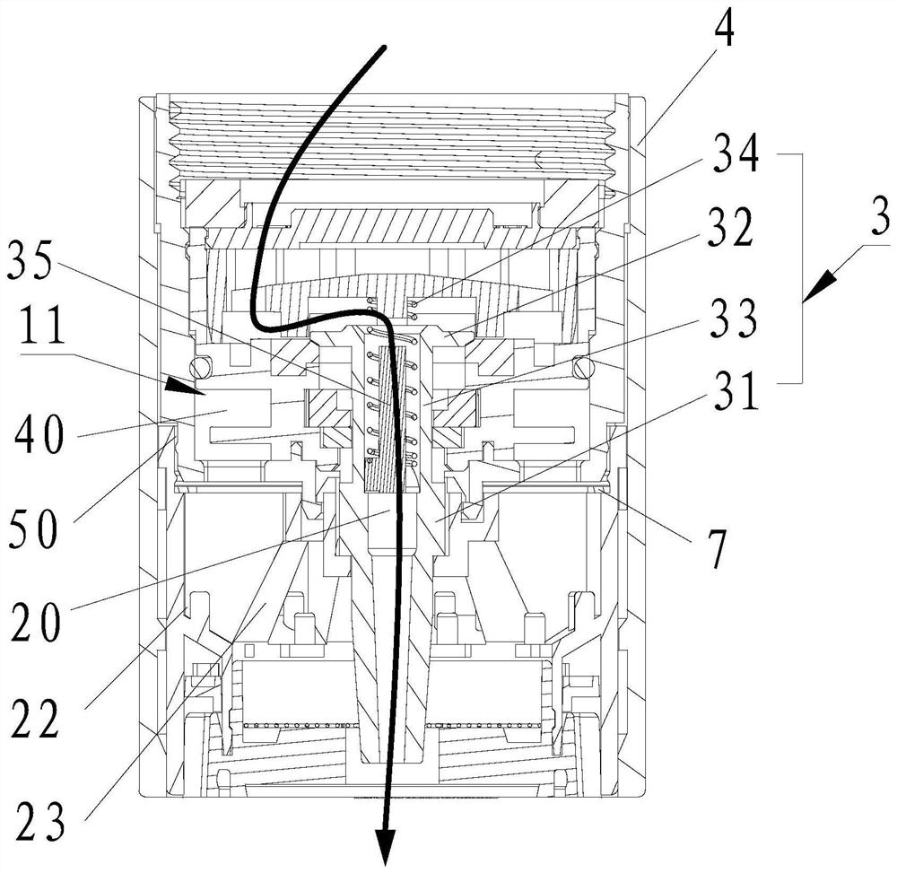
[0103] Please refer to Figure 1-Figure 7 , A water outlet device, comprising a water inlet mechanism 1, a diversion mechanism 2 connected to the water inlet mechanism 1, and a diversion mechanism 3 installed in the water inlet mechanism 1 and passing through the diversion mechanism 2;

[0104] The water inlet mechanism 1 includes a water inlet channel 10;

[0105] The shunt mechanism 3 includes a first water outlet channel 20;
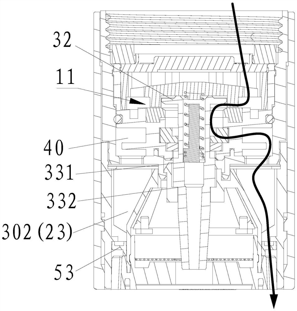
[0106] The diversion mechanism 2 includes a second water outlet channel 301 and a third water outlet channel 302;

[0107] When the flow guiding mechanism 2 moves relative to the flow dividing mechanism 3, the water inlet channel 10 is in communication with the first water outlet channel 20, the second water outlet channel 301 or the third water outlet channel 302.

[0108] Reference Figu...

Example Embodiment

[0131] The second embodiment of the present invention is:

[0132] The difference between this embodiment and the first embodiment is that the specific structure of the water inlet assembly 11 is limited.
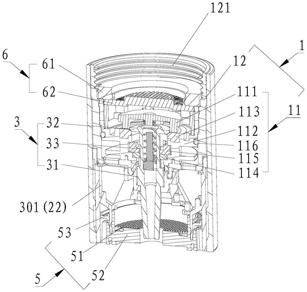
[0133] Please refer to figure 2 , The water inlet assembly 11 includes an upper inlet ring 111, a lower inlet ring 112, a second gasket 113, a third gasket 114, a press buckle 115 and a fourth gasket 116; the second gasket 113 is embedded on the top of the lower inlet ring 112 , The upper inlet ring 111 is embedded in the top of the lower inlet ring 112; the press buckle 115 is horizontally inserted in the outlet of the lower inlet ring 112, and the third gasket 114 is embedded in the lower inlet ring 112 and is located in the press buckle 115 below; the outlet assembly 12 is sleeved on the outside of the lower inlet ring 112; the fourth gasket 116 is sleeved on the outside of the lower inlet ring 112 and inside the outlet assembly 12; the upper ends of the two protrusions 31 a...

Example Embodiment

[0135] The third embodiment of the present invention is:

[0136] The difference between this embodiment and the second embodiment is that the second structure of the flow guiding mechanism 2 and the flow dividing mechanism 3 is defined.

[0137] Refer to Figure 9-12 , The shunt mechanism 3 is provided with a second annular boss 36, and a trapezoidal groove 361 is opened on the lower side of the second annular boss 36 to form two stepped surfaces of different heights, namely, the first stepped surface 3611 and the second stepped surface 3612, the first step surface 3611 is located at the bottom of the second annular boss 36, and the second step surface 3612 is located at the top of the trapezoidal groove 361. The top width of the trapezoidal groove 361 in the rotation direction is smaller than the bottom width of the trapezoid groove 361 in the rotation direction. There are also two oppositely arranged protrusions 31 on the outside of the diverting mechanism 3. The protrusions 31...


PUM


Abstract

The invention discloses a water discharging device which comprises a water feeding mechanism, a flow distributing mechanism and a flow guiding mechanism rotatably connected with the water feeding mechanism. The flow distributing mechanism is arranged in the water feeding mechanism and is arranged in a way of penetrating through the axis of the flow guiding mechanism; the water feeding mechanism comprises a water feeding channel; the flow distributing mechanism comprises a first water discharging channel; the flow guiding mechanism comprises a second water discharging channel and a third waterdischarging channel; and when the flow guiding mechanism moves relative to the flow distributing mechanism, the water feeding channel communicates with the first water discharging channel, the secondwater discharging channel or the third water discharging channel. The invention provides the water discharging device capable of switching various forms of a water flow, and the water discharging device realizes water discharging with three functions within a limited space, and is small in volume and rich in functions.

Description

technical field [0001] The invention relates to the field of sanitary ware, in particular to a water outlet device. Background technique [0002] At present, in order to change the water outlet mode of the faucet, a water outlet device is usually added under the faucet to control or adjust the water outlet volume and water outlet state of the faucet. [0003] In order to make the outer diameter of the water outlet device consistent with the outer diameter of the faucet, the applicant has applied for the following patents: [0004] A water outlet control device (authorized notification number CN104874506B), which discloses a water diversion body and a water guide body, the water diversion body includes a through diversion hole; the water guide body includes a first water inlet, a second water inlet, a first water outlet channel and a second The water outlet channel, the upper space of the first water inlet and the second water inlet are connected, the first water inlet is co...

Claims


Application Information

Patent Timeline
IPC IPC(8): E03C1/08E03C1/084E03C1/086
CPCE03C1/08E03C1/084E03C1/086E03C1/0405E03C1/04
Inventor 周华强
Owner XIAMEN WATER NYMPH SANITARY TECH
Why Eureka
Try Eureka