Drilling equipment with novel drill rod propelling part

A technology of drilling equipment and propulsion parts, which is applied to drilling equipment and methods, drilling equipment, drill pipes, etc., and can solve problems such as drill pipe swings

Pending Publication Date: 2020-10-27
HUBEI SHOUKAI MACHINERY
0 Cites 0 Cited by

AI-Extracted Technical Summary

Problems solved by technology

[0003] The invention provides a drilling device with a new type of drill rod ...

Method used

In order to facilitate precise docking between the drill rods, the drill rod holder 42 also includes a displacement portion, and the displacement portion includes a pair of relative displacement cylinders 428, and the movement of the two displacement cylinders 428 The ends are respectively hinged with the two first holding cylinders 425, the fixed ends of the two first holding cylinders 425 are hinged with the outer shell 41, and the movable end of the displacement cylinder 428 telescopically drives the first holding cylinder 425 relative to the The outer casing 41 rotates to facilitate the adjustment of the docking position between the drill rods.
[0018] Below in conjunction with the accompanying drawings, the principles and features of the present invention are described, and examples are only used to explain the present invention, and are not intended to limit the scope of the present invention. In the following paragraphs the invention is described more specifically by way of example with reference to the accompanying drawings. Advantages and features of the present invention will be ap...

Abstract

The invention provides drilling equipment with a novel drill rod propelling part. The drilling equipment comprises a propelling aiding mechanism. The propelling aiding mechanism comprises an outer shell, a drill rod aiding part, the drill rod propelling part and a drill rod rotating part. The drill rod propelling part comprises a propelling oil cylinder, a movable pulley set, a fixed pulley set, abelt part and a guide assembly. The fixed ends of the fixed pulley set and the propelling oil cylinder are fixed to the outer shell, the movable ends of the movable pulley set and the propelling oilcylinder are fixed, one end of the belt part is fixed to a length adjusting portion, and the other end of the belt part is wound around the fixed pulley set and the movable pulley set. The guide assembly comprises a pair of guide rods and a pair of sliding abutting wheels, the pair of guide rods are arranged on the two sides of a pulley frame in the stretching and shrinking direction of the movable end of the propelling oil cylinder, the guide rods are fixed to the outer shell, the pair of sliding abutting wheels are movably arranged on the faces, facing the guide rods, of the movable pulley set, and the pair of sliding abutting wheel slidingly abut against the pair of guide rods correspondingly.

Application Domain

Drilling rodsConstructions +3

Technology Topic

Leather beltDrill pipe +2

Image

  • Drilling equipment with novel drill rod propelling part
  • Drilling equipment with novel drill rod propelling part
  • Drilling equipment with novel drill rod propelling part

Examples

  • Experimental program(1)

Example Embodiment

[0018] The principles and features of the present invention will be described below with reference to the accompanying drawings. The examples cited are only used to explain the present invention and not to limit the scope of the present invention. In the following paragraphs, the present invention is described in more detail by way of example with reference to the drawings. According to the following description and claims, the advantages and features of the present invention will be clearer. It should be noted that the drawings are in a very simplified form and all use imprecise proportions, which are only used to conveniently and clearly assist in explaining the purpose of the embodiments of the present invention.
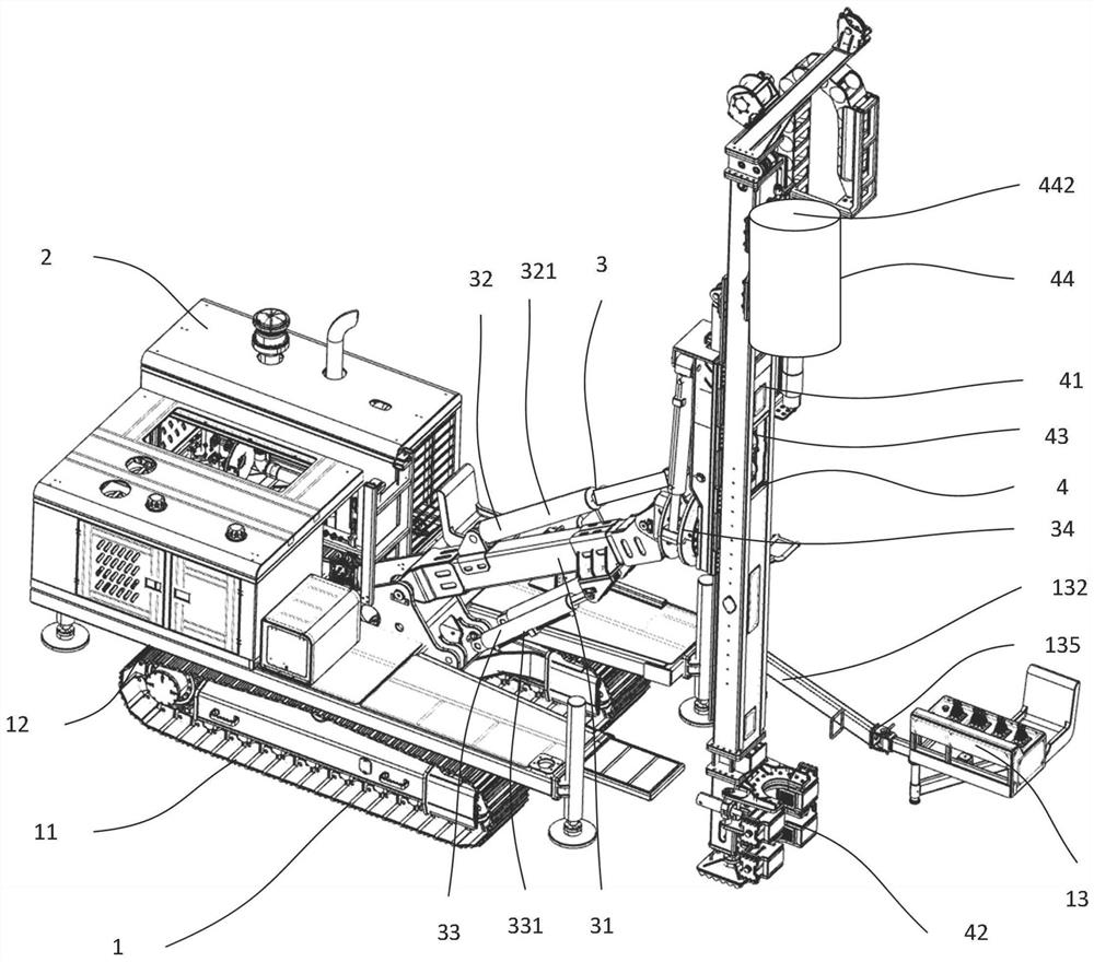
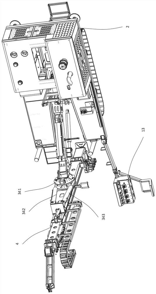
[0019] Such as Figure 1-Figure 2 As shown, it is a drilling equipment provided by an embodiment of the present invention, which includes: a movement mechanism 1, a power mechanism 2, a connection adjustment mechanism 3, a propulsion and holding mechanism 4, a drill rod, the power mechanism 2, the connection The adjustment mechanism 3 is arranged on the movement mechanism 1, the advancing and holding mechanism 4 is connected to the connecting adjustment mechanism 3, and the drill rod is detachably fixed on the advancing and holding mechanism 4.
[0020] The power mechanism 2 is connected to the movement mechanism 1, the connection adjustment mechanism 3, and the advancing and holding mechanism 4 to provide power for the movement mechanism 1, the connection adjustment mechanism 3 and the advancing and holding mechanism 4.
[0021] The connection adjustment mechanism 3 is used for adjusting the posture of the propulsion and holding mechanism 4 relative to the drilling surface.
[0022] The advancing and holding mechanism 4 is used to clamp the drill rod and push the drill rod to move relative to the drilling surface.
[0023] The motion mechanism 1 includes a walking crawler 11 and a working platform 12, the working platform 12 is arranged on the walking crawler 11, the power mechanism 2, the connection adjusting mechanism 3 are fixed on the working platform 12, and The walking crawler 11 is connected to the power mechanism 2, and the power mechanism 2 drives the walking crawler 11 to work.
[0024] Such as figure 1 , Figure 7 , Figure 8 As shown, the motion mechanism 1 further includes a workbench 13, which includes an operating platform 131, a rotating link 132, a lifting member 133, and an operating device 134. One end of the rotating link 132 is connected to the operating device 134. The platform 12 is hinged, and the other end is connected to a hinge part 135 formed by the extension of the fixed end of the lifting member 133. The operating platform 131 is fixed to the movable end of the lifting member 133, and the movable end of the lifting member 133 drives the lifting member 133 moves up and down in the vertical direction, and the operating device 134 is fixed on the operating platform 131.
[0025] The hinge portion 135 includes a first U-shaped piece 1351, a second U-shaped piece 1352, and a pin 1353. The U-shaped open end of the first U-shaped piece 1351 and the U-shaped open end of the second U-shaped piece 1352 Hinged, the other end of the first U-shaped member 1351 is fixed to the fixed end of the lifting member 133, and the other end of the second U-shaped member 1352 is fixed away from the work platform 12 with the rotating link 132, The side wall of the first U-shaped piece 1351 is provided with a plurality of limiting holes evenly arranged along the circumferential direction of the hinge joint of the first U-shaped piece 1351 and the second U-shaped piece 1352. The shaped member 1352 is provided with a butting hole corresponding to the limiting hole, and the pin 1353 passes through one of the limiting hole and the butting hole to make the corresponding first U-shaped member 1351 and the second U-shaped member 1351 and the second The U-shaped pieces 1352 are relatively fixed.
[0026] In this embodiment, the lifting member 133 is a lifting cylinder.
[0027] When in use, adjust the relative position of the first U-shaped piece 1351 and the second U-shaped piece 1352 to make the workbench 13 in a proper position according to requirements, and then make the pins 1353 pass through one of the limiting holes And the docking hole to make the corresponding first U-shaped piece 1351 and the second U-shaped piece 1352 relatively fixed; adjust the extension length of the movable end of the lifting cylinder, so that the operating platform 131 is at Suitable for operators to operate.
[0028] Such as figure 1 , figure 2 As shown, the connecting adjustment mechanism 3 includes a main connecting beam 31, a pitch adjusting member 32, a lifting adjusting member 33, and a rotating member 34. One end of the main connecting beam 31 is hinged to the work platform 12, and the other end is connected to the rotating The member 34 is hinged, the pitch adjusting member 32 is hinged to the main connecting beam 31 and the rotating member 33, and the pitch adjusting member 32 drives the rotating member 34 to rotate in the plane of the main connecting beam 31, so The lifting adjusting member 33 is hinged to the main connecting beam 31 and the work platform 12, the lifting adjusting member 33 drives the rotating member 34 to lift in the vertical direction, and the rotating member 34 is connected to the propulsion and holding mechanism. 4 is fixed, driving the pushing and holding mechanism 4 to rotate in a plane perpendicular to the main connecting beam 31.
[0029] In this embodiment, the pitch adjusting member 32 includes a first telescopic cylinder 321, the fixed end of the first telescopic cylinder 321 is hinged with the main connecting beam 31, and the movable end of the first telescopic cylinder 321 is connected to the main connecting beam 31. The rotating member 34 is hinged, and the movable end of the first telescopic cylinder 321 is extended or contracted to drive the rotating member 34 to rotate relative to the main connecting beam 31.
[0030] The lifting adjustment member 33 includes a second telescopic oil cylinder 331, the fixed end of the second telescopic oil cylinder 331 is hinged with the work platform 12, and the movable end of the second telescopic oil cylinder 331 is hinged with the main connecting beam 31, The movable end of the second telescopic oil cylinder 331 extends or contracts to drive the main connecting beam 31 to rotate relative to the work platform 12.
[0031] In this embodiment, the main connecting beam 31 is the main load-bearing mechanism, and the lifting adjustment member 33 is an important component supporting the main connecting beam 31, so in order to enhance the supporting effect of the main connecting beam 311, The lifting adjustment member 33 includes two second telescopic oil cylinders 331. The fixed ends of the two second telescopic oil cylinders 331 are hinged to different positions of the work platform 12 respectively. The movement of the two second telescopic oil cylinders 331 The end is hinged at the same position as the main connecting beam 31, and the two second telescopic cylinders 331 and the movement mechanism 2 form a stable support triangle to form a stable support for the main connecting beam 31.
[0032] For the rotating member 34, there are multiple implementations. For example, the rotating member 34 includes a rotating motor, the movable end of the rotating motor is fixed to the pushing and holding mechanism 4, and the fixed end of the rotating motor is connected to The main connecting beam 31 and the pitch adjusting member 32 are hinged, and the rotation of the movable end of the moving motor drives the propulsion and holding mechanism 4 to rotate relative to the main connecting beam 31.
[0033] In this embodiment, the rotating member 34 includes a rotating bearing 341, a first auxiliary rotating oil cylinder 342, and a second auxiliary rotating oil cylinder 343. The rotating bearing 341 has a first part and a second part that are relatively rotatable. One part is fixed to the propulsion and holding mechanism 4, the second part is articulated with the main connecting beam 31 and the pitch adjusting member 32; the movable end of the first auxiliary rotating cylinder 342, the second auxiliary rotating cylinder 343 The movable ends are located on both sides of the advancing and holding mechanism 4 and are hinged with the second part. The fixed end of the first auxiliary rotating cylinder 342, the fixed end of the second auxiliary rotating cylinder 343 and the advancing and holding Mechanism 4 is fixed. When the movable end of the first auxiliary rotation cylinder 342 is extended and the movable end of the second auxiliary rotation cylinder 343 is contracted, or when the movable end of the first auxiliary rotation cylinder 342 is contracted and the movable end of the second auxiliary rotation cylinder 343 is stretched For a long time, the advancing and holding mechanism 4 rotates relative to the second part.
[0034] In this way of realizing the rotation of the propulsion and holding mechanism 4, the first auxiliary rotation cylinder 342 and the second auxiliary rotation cylinder 343 jointly provide rotation power, and the rotation power output is more stable.
[0035] Such as figure 1 , image 3 , Figure 4 , Figure 5 , Image 6 As shown, the advancing and holding mechanism 4 includes an outer shell 41, a drill rod holding member 42, a drill rod pushing member 43, and a drill rod rotating member 44. The outer shell 41 is fixed to the rotating member 34, and the drill rod holding 42. The drill rod pushing member 43 is fixed on the outer shell 41, the drill rod rotating member 44 is movably arranged on the outer shell 41 and connected with the drill rod pushing member 43, and the drill The rod pushing member 43 pushes the drill rod rotating member 44 to slide along the outer shell 41.
[0036] The drill rod is fixed to the power output end of the drill rod rotating member 44. While the drill rod rotating member 44 drives the drill rod to rotate, the drill rod pushing member 43 pushes the drill rod rotating member 44 along The outer shell 41 slides, so that the drill rod spirally advances with respect to the drilling surface to realize drilling.
[0037] The outer edge of the outer shell 41 protrudes outward to form a sliding track 411.
[0038] The drill rod holder 42 is used to fix the drill rod when the drill rod is spliced.
[0039] The drill rod holding member 42 includes a holding frame 421, a first holding part 422, and a second holding part 423. The first holding head 422 and the second holding head 423 are arranged along the length of the drill rod at the On the blessing rack 421.
[0040] The first buffing portion 422 includes a pair of first buffing heads arranged oppositely, and the two first buffing heads are disposed oppositely and located on two sides of the drill rod, and are used for buffing the drill rod.
[0041] The first holding head includes a first holding block 424 and a first holding oil cylinder 425. The movable end of the first holding oil cylinder 425 is fixed to the first holding block 424. The movement of the first holding oil cylinder 425 is The ends extend, and the first clamping blocks 424 of the two first holding heads move relative to each other to hold the drill rod.
[0042] In order to enable the first holding heads arranged oppositely to work synchronously, the first holding part 422 also includes a first oil separator. The first oil separator has a first inlet pipe and two first oil outlet pipes. One end of the two first oil outlet pipes is connected to one end of the first inlet pipe, the other end of the first inlet pipe is connected to the oil pump of the power mechanism 2, and the other ends of the two first oil outlet pipes They are respectively connected to the two first buffing cylinders 425, and the oil pump of the power mechanism 2 fills the first buffing cylinder 425 with oil to drive the first buffing cylinder 425 to work.
[0043] The second holding portion 423 includes a pair of oppositely arranged second holding heads, and the two first holding heads are arranged oppositely and located on two sides of the drill rod, and are used for holding the drill rod.
[0044] The second holding head includes a second holding block 426 and a second holding oil cylinder 427. The movable end of the second holding oil cylinder 427 is fixed to the second holding block 426. The movement of the second holding oil cylinder 427 is The ends are elongated, and the second clamping blocks 426 of the two second holding heads move relative to each other to hold the drill rod.
[0045] In order to enable the oppositely arranged second buffing heads to work synchronously, the second buffing portion 423 further includes a second oil separator, which has a second inlet pipe and two second oil outlet pipes One end of the two second oil outlet pipes is connected to one end of the second inlet pipe, the other end of the second inlet pipe is connected to the oil pump of the power mechanism 2, and the other ends of the two second oil outlet pipes They are respectively connected to the two second holding oil cylinders 427, and the oil pump of the power mechanism 2 injects oil into the second holding oil cylinder 427 to drive the second holding oil cylinder 427 to work.
[0046] When in use, when the first drill rod is gradually driven into the drilling surface with the advancement of the drill rod rotating member 44, and the drill rod needs to be spliced ​​again, the second holding head connects the first drill rod The part protruding from the drilling surface is clamped, the drill rod rotating member 44 is reset, one end of the second drill rod is clamped by the first holding head, and the other end of the second drill rod is connected to the drill The rod rotating member 44 is fixed, and the drill rod rotating member 44 rotates and advances, so that the second drill rod and the part of the first drill rod protruding from the drilling surface are spliced ​​into one body. Furthermore, it can be punched further.
[0047] In order to facilitate the precise butt joint between the drill rods, the drill rod holder 42 further includes a displacement part. The displacement part includes a pair of opposed displacement cylinders 428. The movable ends of the two displacement cylinders 428 are connected to each other. The two first holding oil cylinders 425 are hinged, the fixed ends of the two first holding oil cylinders 425 are hinged to the outer housing 41, and the movable end of the displacement oil cylinder 428 telescopically drives the first holding oil cylinder 425 relative to the outer housing 41 41 rotation, convenient to adjust the docking position between drill rods.
[0048] The drill rod propelling member 43 includes a propulsion cylinder 431, a movable pulley set 432, a fixed pulley set 433, a belt member 434, a length adjustment portion 435, and a safety limit portion 436. The fixed pulley set 433 and the fixed end of the propulsion cylinder 431 are fixed On the outer shell 41, the movable pulley set 432 is fixed to the movable end of the propulsion cylinder 431, one end of the belt member 434 is fixed to the length adjusting portion 435, and the other end bypasses the fixed pulley set 433, and Wound on the movable pulley set 432, the length adjustment part 435 is fixed to the drill rod rotating member 44, one end of the safety limit part 436 is fixed to the drill rod rotating member 44, and the other end bypasses the drill rod rotating member 44. The fixed pulley set 433 is fixed to the movable pulley set 432, and the safety limit portion 436 is in a natural relaxation state.
[0049] The movable pulley set 432 includes a pulley frame 4321, a first movable pulley 4322, a second movable pulley 4323, and the first movable pulley 4322, the second movable pulley 4323 is rotatably disposed on the pulley frame 4321.
[0050] The belt member 434 includes a first belt 4341 and a second belt 4342. One end of the first belt 4341 is fixed to the drill rod rotating member 44, and the other end bypasses the first movable pulley 4322 and is connected to the outer shell 41. Fixed, the first belt 4341 makes the drill rod rotating member 44 have a tendency to move toward the drill rod holder 42; one end of the second belt 4342 is fixed to the outer shell 41, and the other end bypasses the The second movable pulley 4323 and the fixed pulley set 433 are fixed to the length adjusting part 435 afterwards, and the second belt 4342 makes the drill rod rotating member 44 have a tendency to be far away from the drill rod supporting member 42.
[0051] Such as Picture 9 As shown, in order to make the movable pulley block 432 move smoothly with the movable end of the propelling cylinder 431, the drill rod propelling member 43 further includes a guide assembly 437, and the guide assembly 437 includes a pair of guide rods 4371. The sliding abutment wheel 4372, a pair of guide rods 4371 are arranged on both sides of the pulley frame 4321 along the telescopic direction of the movable end of the propulsion cylinder 431, the guide rods 4371 are fixed to the outer shell 41, and a pair of guide rods 4371 The sliding abutment wheels 4372 are movably arranged on the surface of the pulley frame 4321 facing the guide rod 4371, and a pair of the sliding abutment wheels 4372 respectively slidably abuts against a pair of the guide rods 4371.
[0052] In this embodiment, the contact surface of the sliding contact wheel 4372 and the guide rod 4371 is formed with an arc surface matching the outer surface of the guide rod 4371.
[0053] The length adjusting portion 435 includes a connecting rod 4351, a fixed bottom plate 4352, a movable cover plate 4353, a gasket 4354, and a fixing bolt 4355. The fixed bottom plate 4352 is fixed to the drill rod rotating member 44, and a plurality of the gaskets 4354 are stacked Is arranged between the fixed bottom plate 4352 and the movable cover plate 4353, and the fixed bolt 4535 passes through the fixed bottom plate 4352, the gasket 4354, and the movable cover plate 4353, so that the fixed bottom plate 4352 The movable cover plate 4353 and the gasket 4354 are fixed to each other, and the connecting rod 4351 is fixed on the movable cover plate 4353 and is fixed to one end of the second belt 4342.
[0054] During use, as the use time accumulates, the belt will be stretched under stress. In order to extend the use time of the belt, the gasket 4534 between the fixed bottom plate 4532 and the movable cover plate 4533 can be gradually removed , Make the distance between the connecting rod 4531 and the second movable pulley 4323 match the length of the second belt; when the last piece of the gasket 4534 is removed, the technicians need to be replaced with a new one. The second belt is 4342.
[0055] The safety limit part 436 includes a safety rope. One end of the safety rope is fixed to the drill rod rotating member 44, and the other end sequentially bypasses the fixed pulley set 433 and the movable pulley set 432, and is fixed to the outer shell. 41 on.
[0056] When the propulsion cylinder 431 is retracted to the minimum state, the length of the part of the safety rope between the fixed pulley block 433 and the drill rod rotating member 44 is slightly less than the length of the drill rod rotating member 44 in the outer shell. The maximum distance to slide on 41.
[0057] When the second belt 4342 is in a normal state, the safety rope is in a loose and unstressed state; and when the second belt 4342 is used for a long time, the second belt 4342 may be broken, so The safety rope will be tightened by force to prevent the drill rod rotating member 44 from contacting the drilling surface under the action of gravity and causing damage.
[0058] The drill rod rotating member 44 includes a sliding bearing plate 441 and a drilling motor 442. The sliding bearing plate 441 is slidably connected to the sliding rail 411, and the drilling motor 442 is fixed on the sliding bearing plate 441. The length adjusting part 435 is fixed on the sliding bearing plate 441.
[0059] The sliding bearing plate 441 is provided with a sliding protrusion 443 at the bottom, a sliding groove is defined on the sliding protrusion 443, and the sliding rail 411 is embedded in the sliding groove.
[0060] The drill rod is fixed to the movable end of the drilling motor 442, the movable end of the drilling motor 442 drives the drill rod to rotate, and the drill rod pushing member 43 drives the drill rod to move to realize spiral drilling .
[0061] In order to facilitate the fastening and splicing between the drill rods, the thinner end of the drill rod is provided with an external thread, and the other end of the drill rod is provided with a splicing groove. The inner diameter of the splicing groove is the same as that of the drill. The thinner end of the rod has the same outer diameter, and the inner surface of the splicing groove is provided with an inner thread matching the outer thread.
[0062] The screwing directions of the external thread and the internal thread are the same as the rotation direction of the movable end of the drilling motor 442. In this way, when the movable end of the drilling motor 442 drives the drill rod to rotate, the connection between the drill rods will be closer.
[0063] The invention is provided with a pair of guide rods and a pair of sliding abutment wheels to make the movable pulley group move strictly along the guide rods to avoid shaking of the movable pulley group during the traveling process, which affects the success rate of punching.
[0064] The above are only the preferred embodiments of the present invention, and are not intended to limit the present invention in any form; any person of ordinary skill in the industry can smoothly implement the present invention as shown in the accompanying drawings of the specification and described above. ; However, all those who are familiar with the profession make use of the technical content disclosed above to make minor changes, modifications and evolutionary equivalent changes without departing from the scope of the technical solution of the present invention, all of which are equivalent implementations of the present invention At the same time, any equivalent changes, modifications, and evolutions made to the above embodiments based on the essential technology of the present invention still fall within the protection scope of the technical solution of the present invention.

PUM

no PUM

Description & Claims & Application Information

We can also present the details of the Description, Claims and Application information to help users get a comprehensive understanding of the technical details of the patent, such as background art, summary of invention, brief description of drawings, description of embodiments, and other original content. On the other hand, users can also determine the specific scope of protection of the technology through the list of claims; as well as understand the changes in the life cycle of the technology with the presentation of the patent timeline. Login to view more.
Why Eureka
Try Eureka