
Transmission shaft connecting flange shock-absorbing protection device

A protection device and transmission shaft technology, which is applied in the direction of spring/shock absorber, coupling, rigid shaft coupling, etc., can solve the problems of transmission shaft impact, vibration difficult to eradicate, equipment vibration, etc.

Pending Publication Date: 2020-10-27
SHANDONG IRON & STEEL CO LTD
View PDF0 Cites 1 Cited by
  • Summary
  • Abstract
  • Description
  • Claims
  • Application Information

AI Technical Summary

Problems solved by technology

[0002] In metallurgical equipment, some large-tonnage or high-torque equipment uses a universal joint shaft for transmission. Usually, the transmission shaft is connected to the reducer, and the engine transmits the torque to the reducer through the drive shaft. On the other hand, there is a deviation between the axis center of the transmission shaft and the transmission shaft, which causes equipment vibration, which is difficult to eradicate. In addition, equipment vibration and other reasons will have impact on the transmission shaft. The parts of the cross package and the reducer or motor are damaged, which will affect the stability and service life of the equipment
[0003] Most of the damping structures in the prior art use rubber gaskets installed between the connecting flanges. The damping effect of this damping structure is limited and cannot achieve a good damping effect. Therefore, it is necessary to design a damping The device eliminates the impact of the transmission shaft vibration on the equipment

Method used


Image

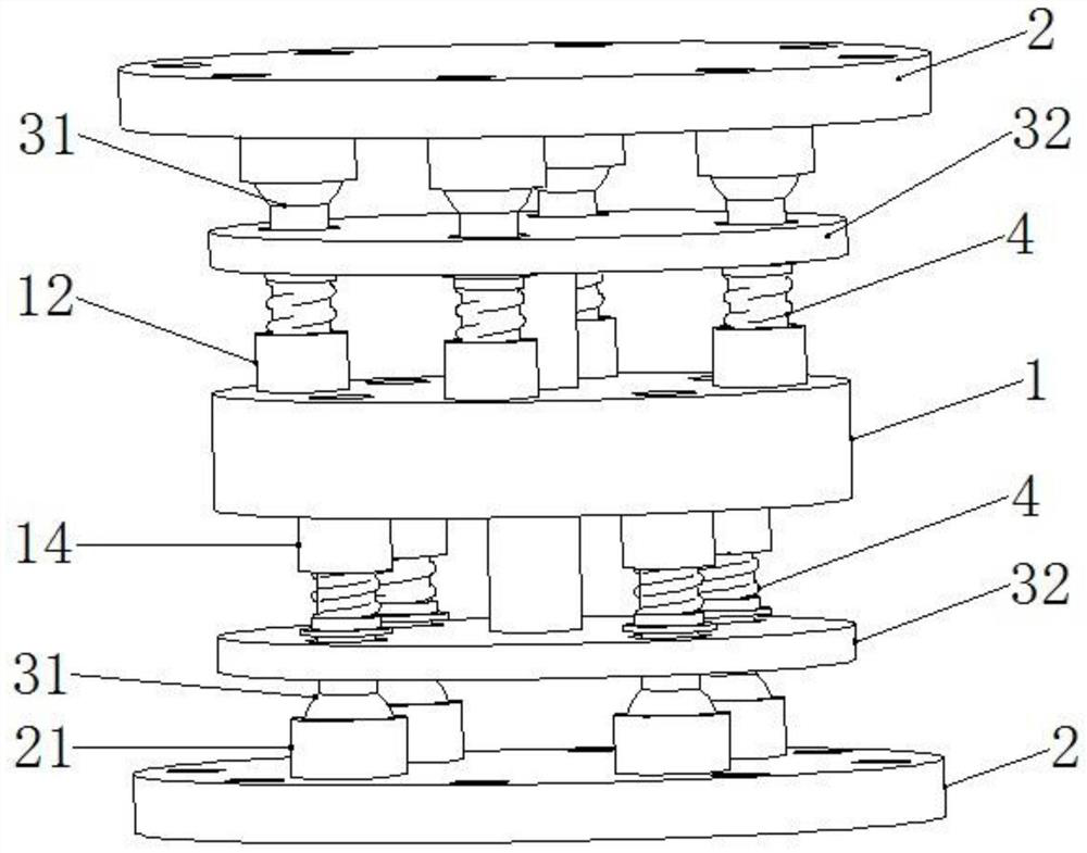
  • Transmission shaft connecting flange shock-absorbing protection device
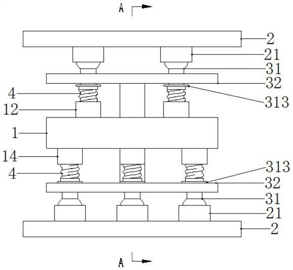
  • Transmission shaft connecting flange shock-absorbing protection device
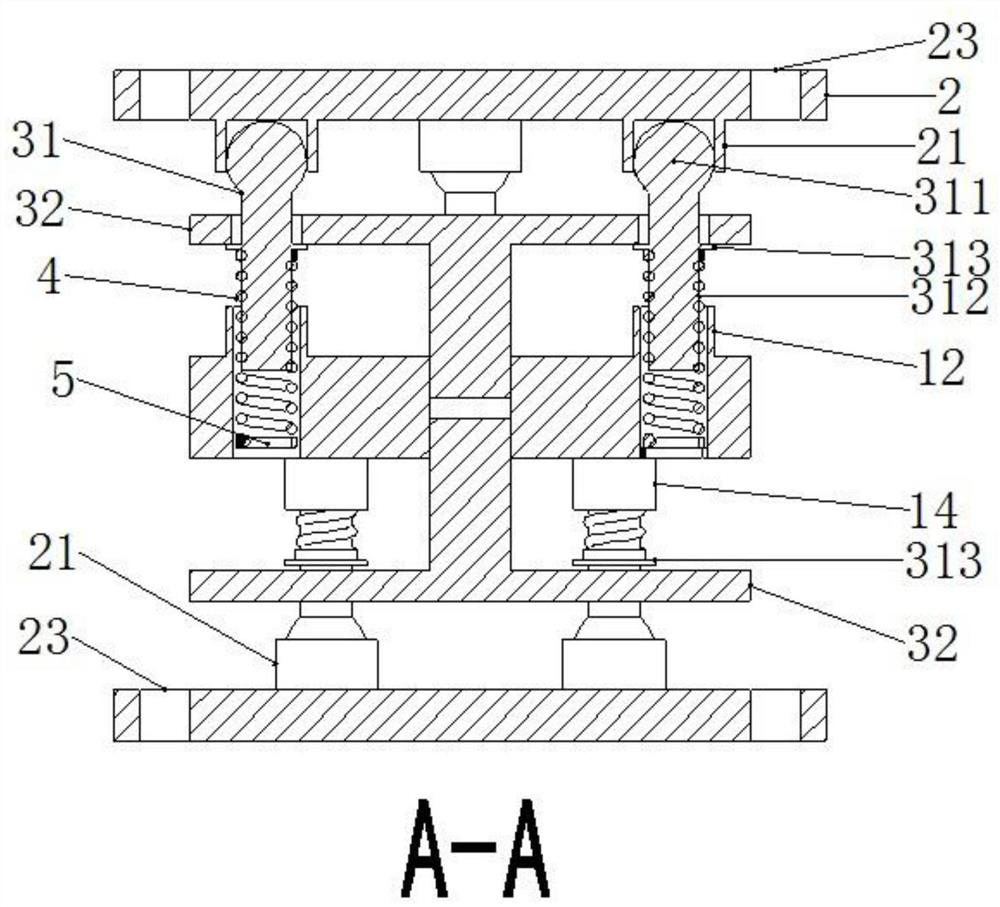
  • Transmission shaft connecting flange shock-absorbing protection device

Examples


Embodiment Construction

[0035] The present invention will be described in detail below with reference to the accompanying drawings and examples. It should be noted that, in the case of no conflict, the embodiments of the present invention and the features in the embodiments can be combined with each other.

[0036] In the description of the present invention, the terms "longitudinal", "transverse", "upper", "lower", "front", "rear", "left", "right", "vertical", "horizontal", " The orientations or positional relationships indicated by "top", "bottom", etc. are based on the orientations or positional relationships shown in the drawings, and are only for the convenience of describing the present invention and do not require that the present invention must be constructed and operated in a specific orientation, so they cannot be understood as Limitations on the Invention. The terms "connected" and "connected" used in the present invention should be understood in a broad sense, for example, it can be fixe...


PUM


Abstract

The invention provides a transmission shaft connecting flange shock-absorbing protection device. The transmission shaft connecting flange shock-absorbing protection device includes a shock-absorbing disc, connecting discs, and shock-absorbing connectors; a through hole is arranged on the shock-absorbing disc, and a shock-absorbing spring is installed in the through hole; two connecting discs are arranged, and the two connecting discs are arranged oppositely above and below the shock-absorbing disc, which are a first connecting disc and a second connecting disc; a ball head hole is arranged oneach connecting disc; the two connecting discs are used for connecting a transmission shaft and a reducer; two shock-absorbing connectors are arranged, which are arranged oppositely along the two sides of the shock-absorbing disc; each shock-absorbing connector is arranged between the shock-absorbing disc and the connecting disc; one end of the shock-absorbing connector is installed in the ball head hole of the connecting disc, and the other end is installed in the through hole of the shock-absorbing disc, so as to be used for shock absorption by cooperating with a shock-absorbing spring; andthe shock-absorbing connectors are also connected to the shock-absorbing disc for transmitting torque. The transmission shaft connecting flange shock-absorbing protection device has a good shock-absorbing effect, can improve the operation stability and service life, has a simple structure, is convenient to install, and is convenient for industrialization promotion and use.

Description

technical field [0001] The invention belongs to the technical field of shock absorption of transmission equipment in the field of metallurgical equipment, and in particular relates to a shock absorption protection device for connecting flanges of transmission shafts. Background technique [0002] In metallurgical equipment, some large-tonnage or high-torque equipment uses a universal joint shaft for transmission. Usually, the transmission shaft is connected to the reducer, and the engine transmits torque to the reducer through the drive shaft. On the other hand, there is a deviation between the axis center of the transmission shaft and the transmission shaft, which causes equipment vibration, which is difficult to eradicate. In addition, equipment vibration and other reasons will have impact on the transmission shaft. The parts of the cross package, the reducer or the motor are damaged, which will affect the stability and service life of the equipment. [0003] Most of the ...

Claims


Application Information

Patent Timeline
IPC IPC(8): F16F15/04F16F15/06F16D1/033
CPCF16D1/033F16F15/046F16F15/06
Inventor 赵国庆李雪涛孙波林雅琴李发宏尹建强李山峰张燕孔峰张戈顾琳琳赵峥
Owner SHANDONG IRON & STEEL CO LTD
Learn More