
Zero-impact spring steel ball safety clutch
A safety clutch, steel ball technology, applied in clutches, automatic clutches, mechanical equipment, etc., can solve problems such as the maximum working torque limit
- Summary
- Abstract
- Description
- Claims
- Application Information
AI Technical Summary
Problems solved by technology
Method used
Image

Examples
Embodiment Construction
[0050] Necessary explanation: In the main text of this manual and all the drawings, the same or similar components and their characteristic parts use the same symbols, and they will only be explained in detail when they appear for the first time, and will not be repeated when they appear again. Give repeated elaboration.
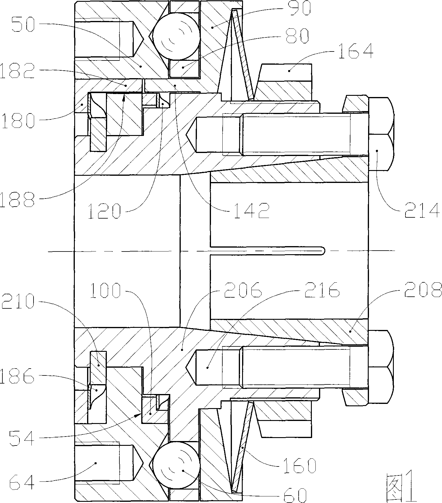
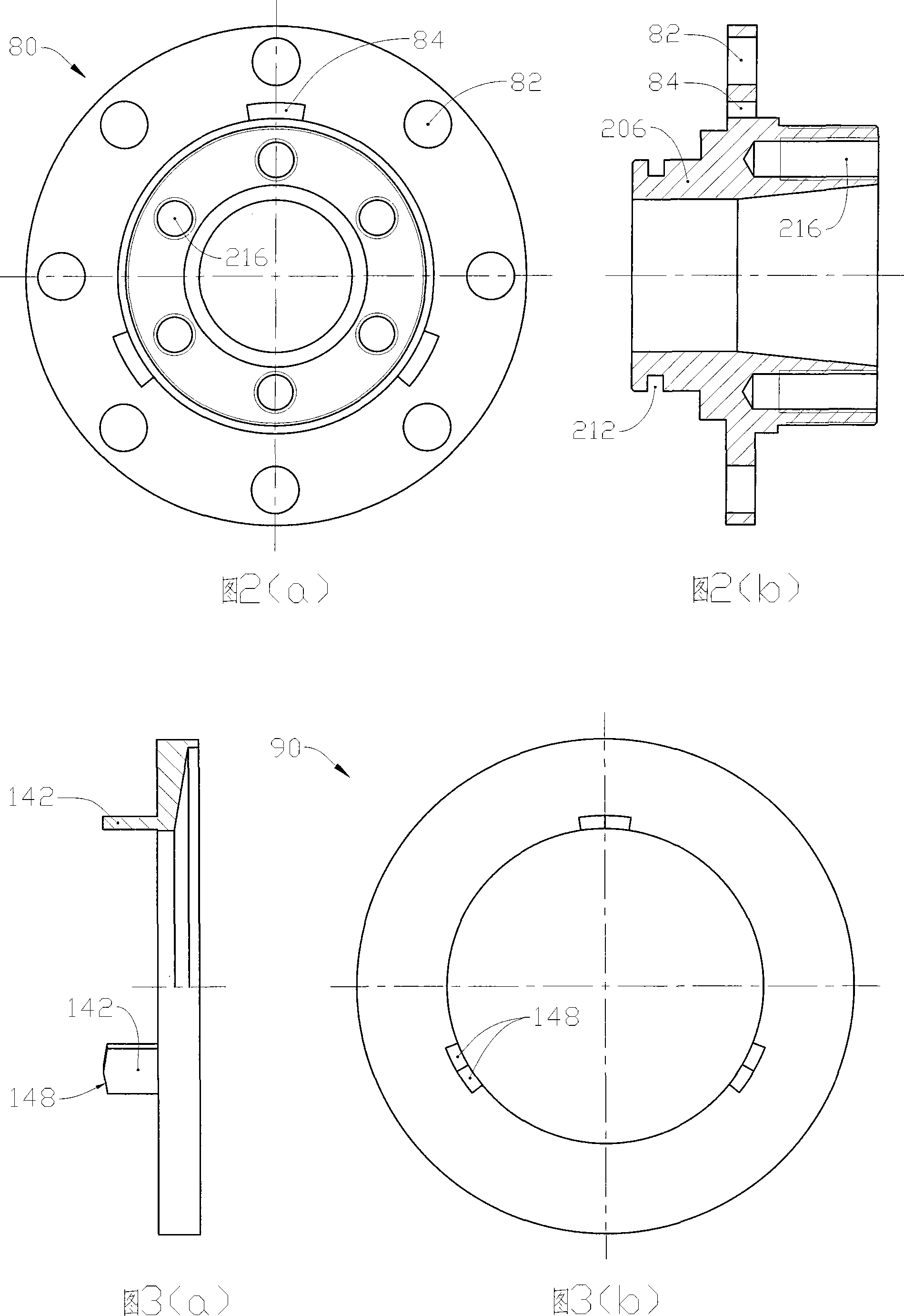
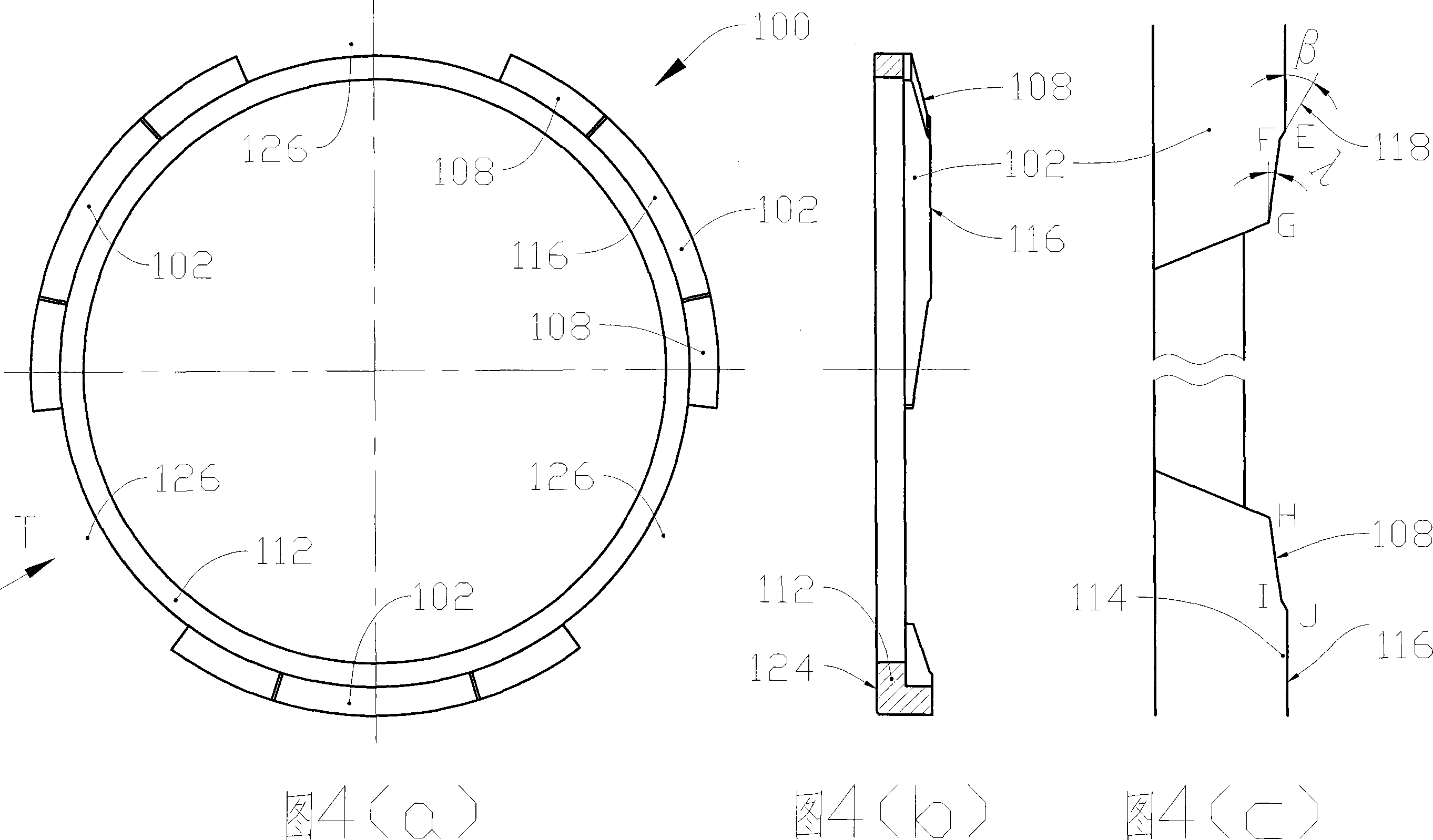
[0051] Figures 1 to 5 show the first embodiment of the present invention, which has the most typical structure of a spring steel ball safety clutch. As shown in FIG. 1, the fixed joint element 50 is sleeved on the outer cylindrical surface of the unthreaded end of the second sleeve 206 by one end of the steel ball hub 80, and is axially fixed by the snap ring 210. The second sleeve 206 and the steel ball hub 80 are made into a rigid body, as shown in FIG. 2. The blocking ring 100 is placed in the circular cavity of the fitting end of the fixing joint element 50. The restraining spring 120 is installed between the blocking ring 100 and the steel ball hub 80 to fo...
PUM
 Abstract
Description
Claims
Application Information