Double-phase shock wave swing rod type high-speed internal combustion engine

A technology of internal combustion engine and shock wave, applied in the direction of mechanical equipment, machine/engine, valve details, etc., can solve the problems of internal combustion engine life shortening, large volume, complex structure, etc., and achieve the effect of compact structure

Inactive Publication Date: 2011-06-15
SICHUAN UNIV
View PDF6 Cites 14 Cited by
  • Summary
  • Abstract
  • Description
  • Claims
  • Application Information

AI Technical Summary

Problems solved by technology

Since this kind of internal combustion engine relies on the linear motion of the piston and the planar motion of the connecting rod to press and drive the crankshaft to rotate, there is a large friction between the kinematic pairs, resulting in low transmission efficiency of the internal combustion engine.
The crankshaft connecting rod type internal combustion engine also has the following main disadvantages: large volume; large unbalanced centrifugal force on the connecting rod and crankshaft; large impact and large vibration; and thus cause large mechanical wear, shortening the life of the internal combustion engine; complex structure, Processing, manufacturing, assembly, etc. are more difficult
[0003] In addition, the general internal combustion engine and the transmission device are two independent machines. Usually, the internal combustion engine needs to be equipped with a transmission for subsequent speed change, resulting in a bulky

Method used


Image

  • Double-phase shock wave swing rod type high-speed internal combustion engine
  • Double-phase shock wave swing rod type high-speed internal combustion engine
  • Double-phase shock wave swing rod type high-speed internal combustion engine

Examples


Embodiment Construction

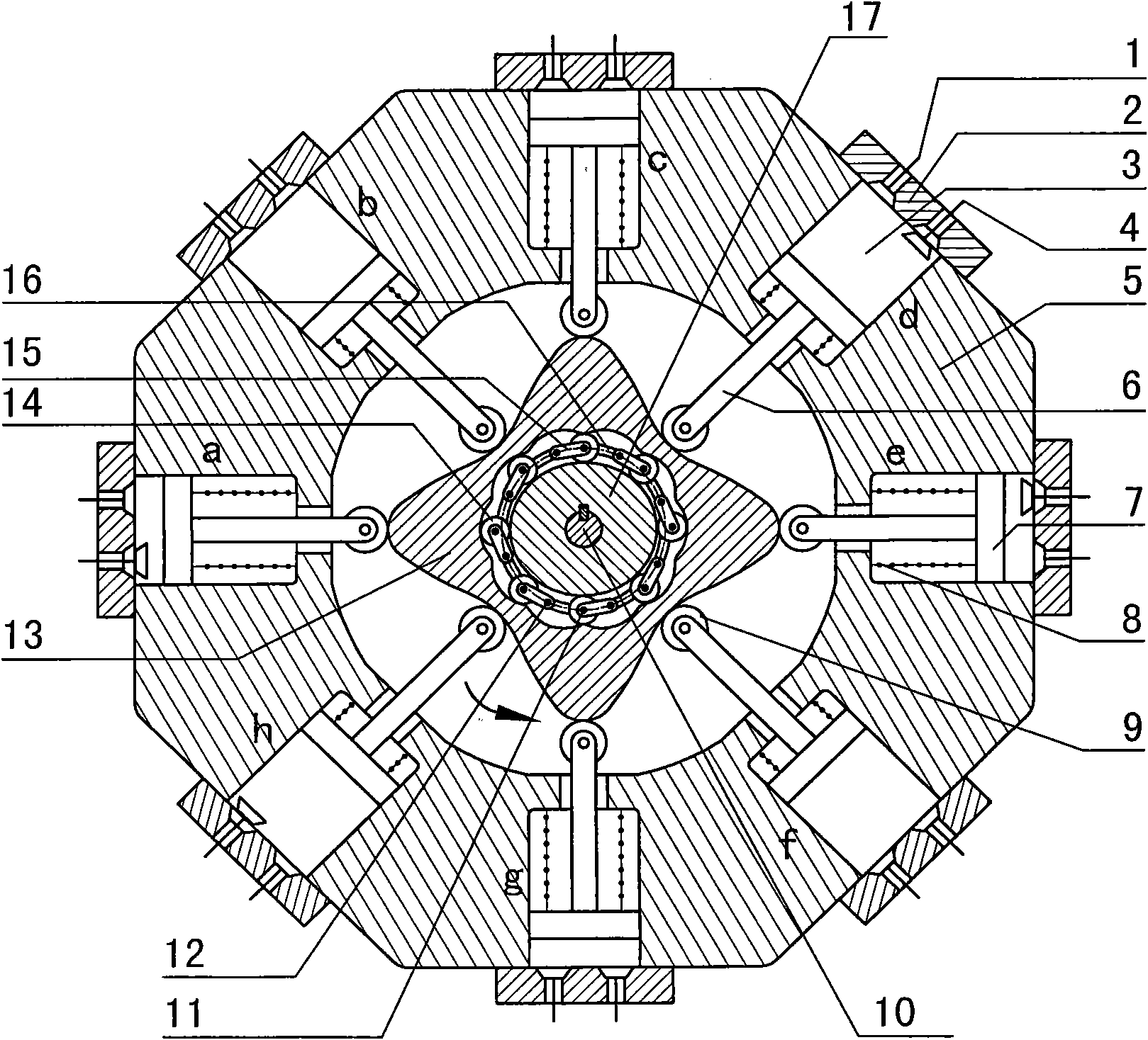
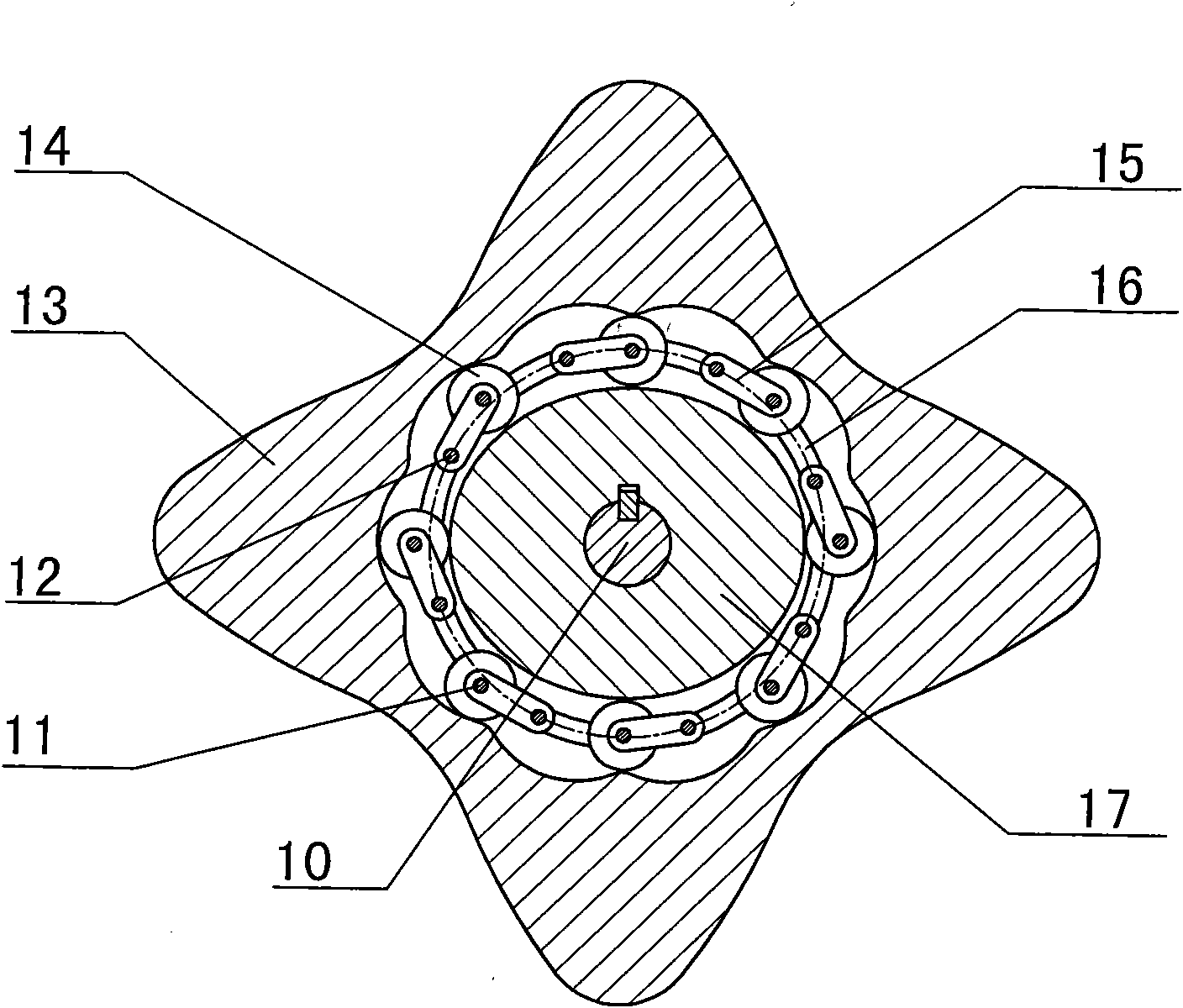
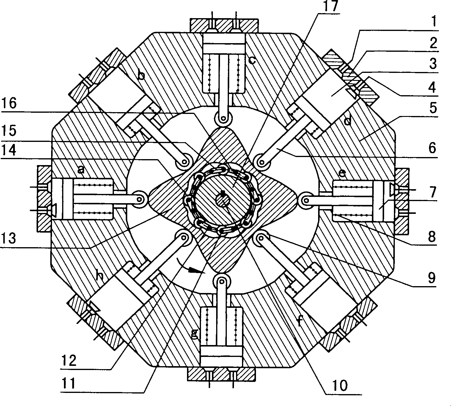
[0037] figure 1 , figure 2 The shown two-phase shock swing rod high-speed internal combustion engine consists of an intake valve (1), a cylinder head (2), a cylinder (3), an exhaust valve (4), a cylinder block (5), a push rod (6), Piston (7), spring (8), roller (9), output shaft (10), movable tooth pin (11), pendulum pin (12), convex inner center wheel (13), movable tooth (14 ), fork (15), movable rack (16), two-phase shock wheel (17) and other components. The eight cylinders (3) are evenly distributed in a circular shape around the convex inner center wheel (13) axisymmetrically, and the angle between two adjacent cylinders is 45°. There is a piston (7) in each cylinder (3), and one end of the push rod (6) is solidified with the piston (7), and the other end is equipped with a roller (9), and the roller (9) makes the push rod (6) The connection with the outer convex inner center wheel (13) is a rolling friction connection. One end of the spring (8) is fixed on the bottom ...


PUM


Abstract

The invention discloses a double-phase shock wave swing rod type high-speed internal combustion engine, and relates to the field of fuel gas power. The invention provides a novel internal combustion engine, wherein eight cylinders are annularly, symmetrically and uniformly distributed around a convex inner central wheel, so that the resultant force borne by the convex inner central wheel is zero; cylinder pistons directly act on the convex inner central wheel through push rods; and the power is transmitted to an output shaft connected with a double-phase shock wave wheel key from the convex inner central wheel through a movable tooth transmission of a double-phase shock wave swing rod. In the internal combustion engine, a connecting rod and a crankshaft in the traditional internal combustion engine are omitted; and a double-phase shock wave swing rod transmission mechanism in the convex wheel has no eccentric mass and has the advantage of automatic balance of inertia force and working load. The revolution speed of the output shaft depends on the transmission rate of the movable tooth transmission; if a movable tooth rack is fixed, the double-phase shock wave wheel outputs power at a high speed; the internal combustion engine can be widely applied to the fields in need of high revolution speed, such as small generators, helicopter engines and the like; and when the output revolution speed is regular, the emission of harmful gases can be reduced. The internal combustion engine has the advantages of simple and compact structure, small axial size, automatic stress balance and stability in operation.

Description

technical field [0001] The invention relates to the field of gas power, more specifically, a two-phase shock wave swing rod type high-speed internal combustion engine. Background technique [0002] At present, the common internal combustion engines are mostly four-stroke crankshaft connecting rod internal combustion engines. The transmission structure of this internal combustion engine all adopts a crank connecting rod mechanism, and the crankshaft is driven by the connecting rod, thereby converting the linear motion of the piston into the rotary motion of the crankshaft. Because this internal combustion engine presses and drives the crankshaft to rotate by the linear motion of the piston and the planar motion of the connecting rod, there is greater friction between the kinematic pairs, resulting in low transmission efficiency of the internal combustion engine. The crankshaft connecting rod type internal combustion engine also has the following major disadvantages: large vol...

Claims


Application Information

Patent Timeline
Patent Type & Authority Applications(China)
IPC IPC(8): F02B75/22F01L1/06
Inventor 梁尚明黄博
Owner SICHUAN UNIV
Why Eureka
Try Eureka