Disc loading mechanism in a disc player for positioning a disc and an optical pickup while reducing mechanical shocks to the disc tray

a disc player and disc technology, applied in the direction of instruments, casings/cabinets/drawers, electrical apparatus, etc., can solve problems such as exerting influence, and achieve the effects of eliminating collision sounds, eliminating shocks, and improving loading gears

Inactive Publication Date: 2001-05-08
SONY CORP
View PDF10 Cites 15 Cited by
  • Summary
  • Abstract
  • Description
  • Claims
  • Application Information

AI Technical Summary

Benefits of technology

It is, therefore, an object of the invention to provide a novel disc tray loading mechanism by improving a loading gear for pulling a disc tray into a casing, eliminating a collision sound which is normally generated upon completion of the pull-in operation of the disc tray and eliminating a shock to the disc player by such collision, thereby improving the quality of a disc player.

Problems solved by technology

However, in such a disc tray loading mechanism a, there are problems such that when the disc tray b reaches the pull-in position, the abutting member e abuts on the stopper member m on the casing side and a collision sound is generated and that a shock due to the collision is fairly propagated to the mechanical deck n or the circuit board or the like an adverse influence is exerted on the disc player having an optical system.

Method used


Image

  • Disc loading mechanism in a disc player for positioning a disc and an optical pickup while reducing mechanical shocks to the disc tray
  • Disc loading mechanism in a disc player for positioning a disc and an optical pickup while reducing mechanical shocks to the disc tray
  • Disc loading mechanism in a disc player for positioning a disc and an optical pickup while reducing mechanical shocks to the disc tray

Examples


Embodiment Construction

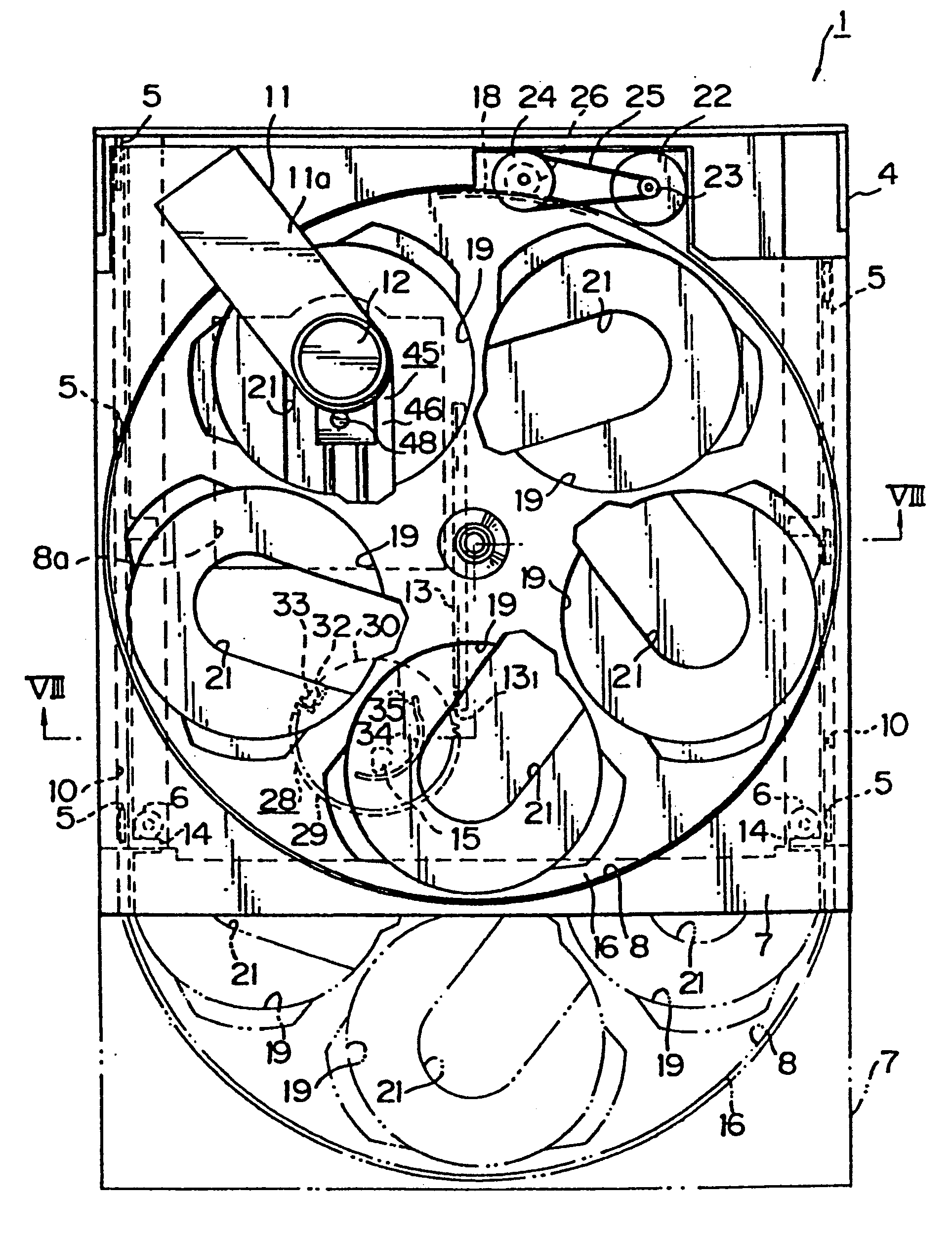
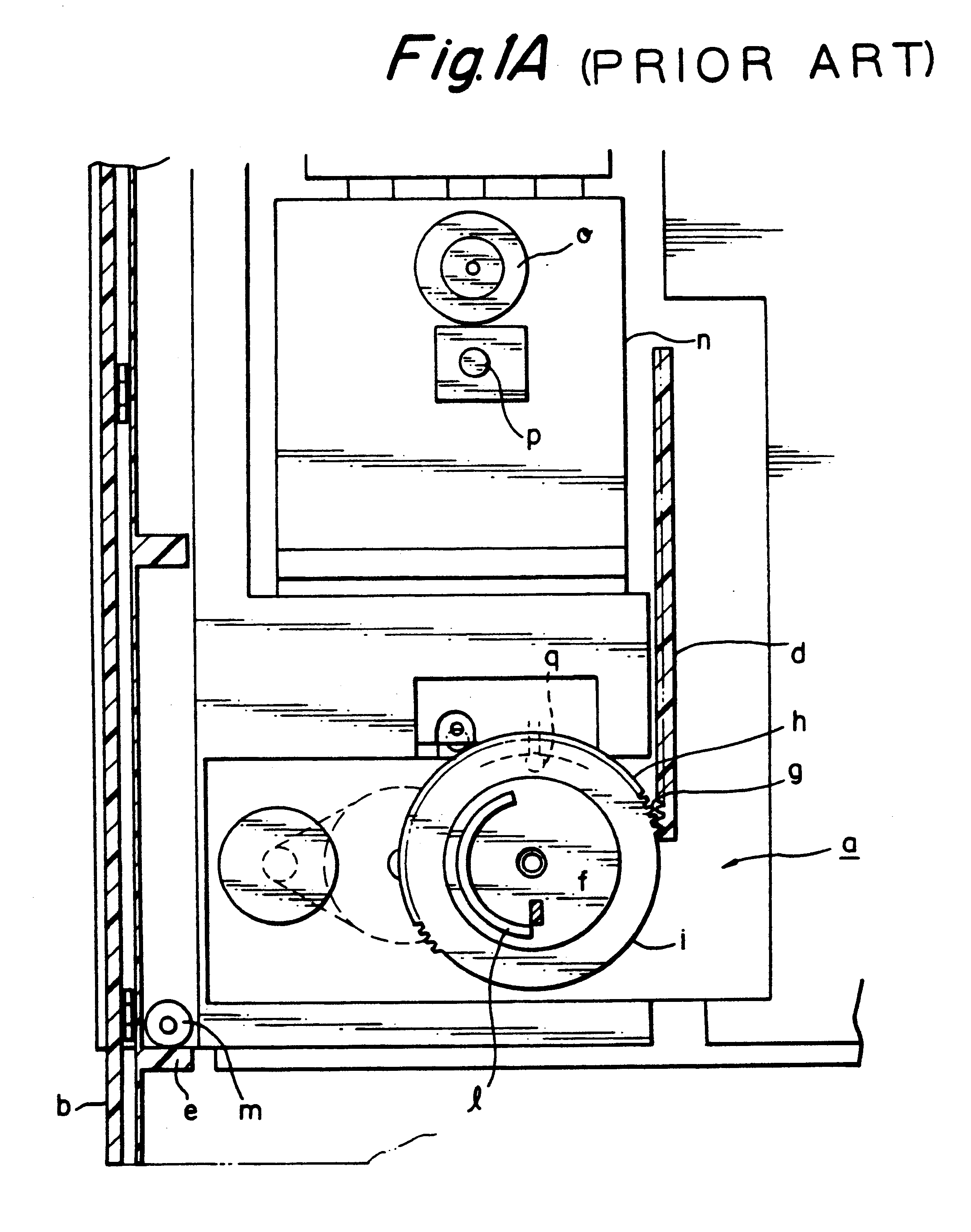
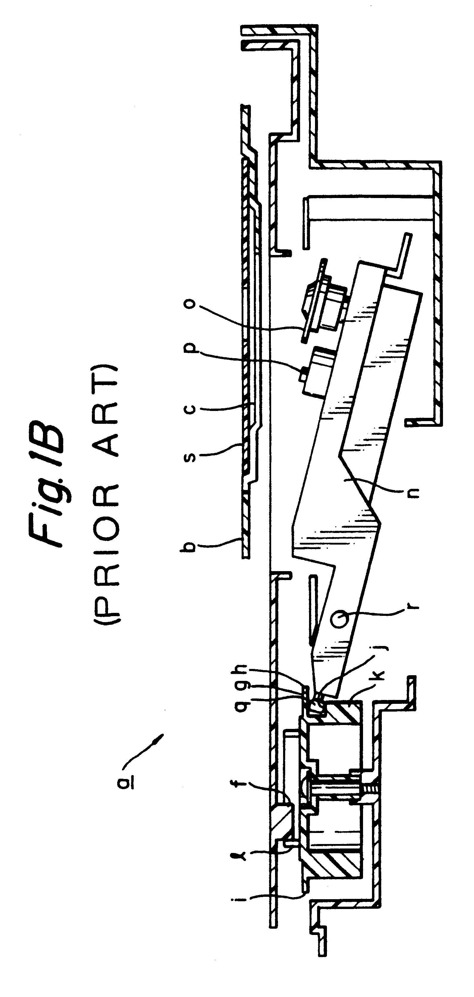
A disc tray loading mechanism of the invention will be described in detail hereinbelow in accordance with an embodiment shown in the drawings (FIGS. 3 to 16).

The embodiment shown in the drawings relates to the case where the disc tray loading mechanism of the invention is applied to a disc player of what is called an automatic changing type in which a plurality of compact discs are enclosed and one of the compact discs is selected and the reproduction is executed, wherein after completion of the pull-in operation of a disc tray, a mechanical deck is raised and the chucking of the compact disc is executed.

a. Casing (FIGS. 3 to 8)

Reference numeral 1 denotes a disc player.

Reference numeral 2 denotes an outer casing of the disc player 1. The outer casing 2 is formed into a relatively thin box shape whose lower and rear surfaces are opened. (The direction which is directed to the left oblique downward position in FIG. 3 assumes the front side and the direction which is directed to the ri...


PUM

PropertyMeasurementUnit
center span angleaaaaaaaaaa
center angleaaaaaaaaaa

Abstract

A loading mechanism of a disc tray onto which recording medium discs such as compact discs, laser discs, or the like are set and which moves between a pull-out position at which the disc tray was pulled out of an outer casing and a pull-in position at which the disc tray was pulled into the outer casing. The engagement between the loading gear and the rack of the disc tray is released just before the pull-in operation of the disc tray is completed and, at the same time, a cam portion formed on the loading gear comes into engagement with the abutted portion of the disc tray, thereby allowing the disc tray to be subsequently pulled in by the pressing motion of the cam portion to the abutted portion. Thus, the pull-in speed of the disc tray can be reduced just before the completion of the pull-in operation of the disc tray and a shock which occurs upon completion of the pull-in operation of the disc tray can be reduced. Due to this, a shock sound by the collision of the disc tray and the member on the casing side for restricting the pull-in position of the disc tray and the shock to the disc player by such a collision are eliminated, thereby raising the quality of the disc player.

Description

BACKGROUND OF THE INVENTION1. Field of the InventionThe invention relates to a novel disc tray loading mechanism. More particularly, the invention relates to a loading mechanism of a disc tray onto which recording medium discs such as compact discs, laser discs, or the like are set and which moves between a pull-out position at which the disc tray is pulled out of an outer casing and a pull-in position at which the disc tray is pulled into the outer casing.2. Description of the Prior ArtThere is a disc player using a known disc tray loading mechanism known as a linear skating type in which a tray on which a recording medium disc is set is pulled into the casing of the player substantially in a horizontal direction.In a disc player of the type mentioned above, since a chucking of the recording medium disc is executed after completion of the loading of the disc tray, it is necessary to raise the disc tray or to lower the mechanical deck.The tray loading mechanism of such a linear skat...

Claims


Application Information

Patent Timeline
Patent Type & Authority Patents(United States)
IPC IPC(8): G11B33/08G11B17/22G11B17/26G11B17/04
CPCG11B17/056G11B17/226G11B17/26G11B33/08
Inventor KUROSU, TADAO
Owner SONY CORP
Why Eureka
Try Eureka