Gear adjusting structure of coffee bean grinder and gear calibration method thereof
A gear adjustment and bean grinder technology, applied in coffee mills, spice mills, household appliances, etc., can solve the problems of high manufacturing precision, inconvenient use, complex structure, etc., and achieve fewer working steps, convenient production, and calibration The effect of convenience
- Summary
- Abstract
- Description
- Claims
- Application Information
AI Technical Summary
Problems solved by technology
Method used
Image
Examples
Embodiment 1
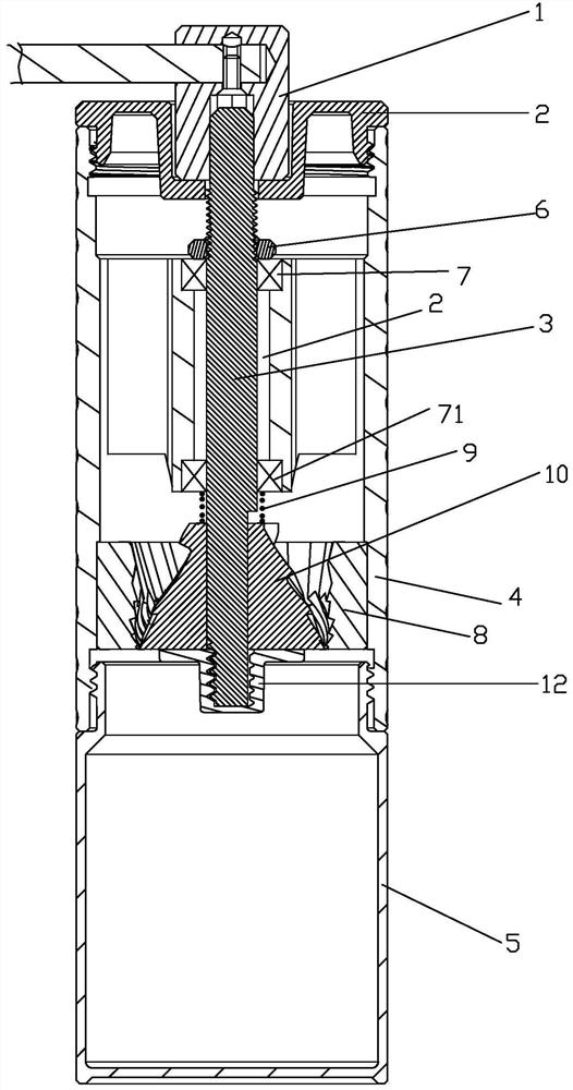
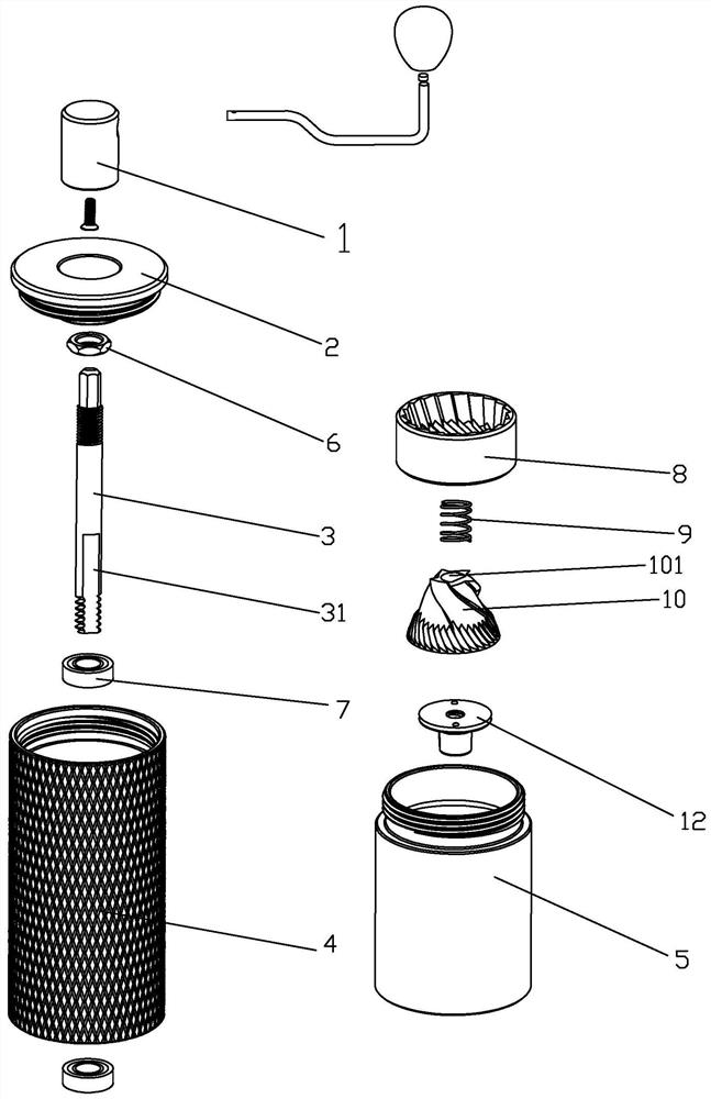
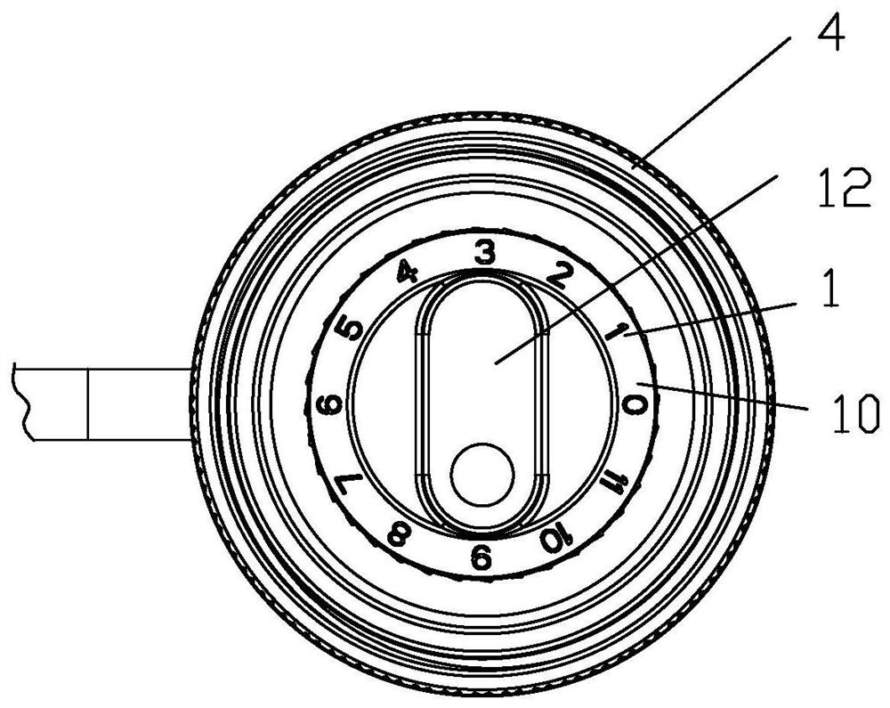
[0039] Embodiment 1: as figure 1 , figure 2 , image 3 , Figure 4 , Figure 5 , Figure 6 As shown, a gear adjustment structure of a hand-operated coffee grinder includes a main body 4, a main shaft 3, a grinding disc ring 8, and a grinding disc core 10. The grinding disc ring 8 is fixed in the inner cavity of the main body 4, and the grinding disc core 10 is located in the grinding disc In the circle; the upper end of the main shaft is screwed with the adjusting nut 6; the main body 4 is provided with a rotatable supporting member, which supports the lower end surface of the adjusting nut 6, and the supporting member can be a bearing 7, or other supporting components or objects, mainly It can support the adjusting nut. The lower part of the main shaft is connected with the grinding disc core 10 through the interlocking structure that can drive the grinding disc core 10 to rotate together. The grinding disc core 10 can move along the main shaft. Adjust the gap between ...
Embodiment 2
[0048] Embodiment 2: as figure 1 , figure 2 , image 3 , the feature of this example is that the interlocking structure includes a central hole 101 provided by the grinding disc core 10 and a main shaft lower part 31 passing through the central hole, the cross section of the central hole 101 is non-circular, and the cross section of the main shaft bottom is the same as The holes match. Compact structure. All the other are with embodiment 1.
Embodiment 3
[0049] Embodiment 3: as Figure 6 , Figure 7As shown, the feature of this example is that the interlocking structure includes a middle hole 101 provided by the grinding disc core 10 and the lower part 31 of the main shaft 3 passing through the middle hole, the hole wall of the middle hole is provided with a keyway 102, and the lower part of the main shaft A protrusion 32 is provided, the width of which matches the width of the keyway, and the protrusion 32 extends into the keyway 102. During assembly or adjustment, when the disc core moves axially along the main shaft, the protrusion can slide along the keyway. All the other are with embodiment 1. The boss in this example can be made by stamping. The interlocking structure is easy and simple to manufacture. When in use, the main shaft drives the grinding disc core to rotate through the protrusion.
PUM
 Abstract
Description
Claims
Application Information
 - R&D
- Intellectual Property
- Life Sciences
- Materials
- Tech Scout
- Unparalleled Data Quality
- Higher Quality Content
- 60% Fewer Hallucinations
Browse by: Latest US Patents, China's latest patents, Technical Efficacy Thesaurus, Application Domain, Technology Topic, Popular Technical Reports.
© 2025 PatSnap. All rights reserved.Legal|Privacy policy|Modern Slavery Act Transparency Statement|Sitemap|About US| Contact US: help@patsnap.com


