High-stability adjustable electric industrial brush

A high-stability, adjustable technology, applied in cleaning methods using tools, cleaning methods using liquids, cleaning methods and utensils, etc., can solve problems such as inability to flexibly handle irregular objects and inconvenient adjustments

Inactive Publication Date: 2020-10-30
安徽环美刷业股份有限公司
View PDF16 Cites 0 Cited by
  • Summary
  • Abstract
  • Description
  • Claims
  • Application Information

AI Technical Summary

Problems solved by technology

[0004] The purpose of the present invention is to solve the problem that the industrial brush in the prior art is inconvenient to adjust and cannot handle irregular objects flexibly, and proposes a high-stability adjustable electric industrial brush

Method used


Image

  • High-stability adjustable electric industrial brush
  • High-stability adjustable electric industrial brush
  • High-stability adjustable electric industrial brush

Examples


Embodiment 1

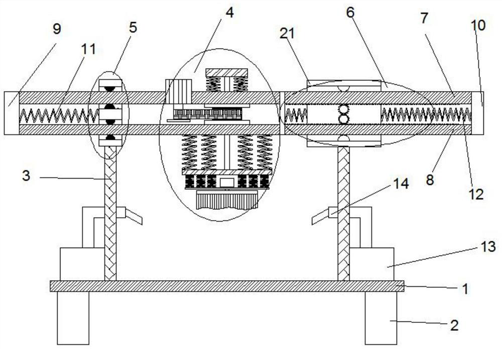
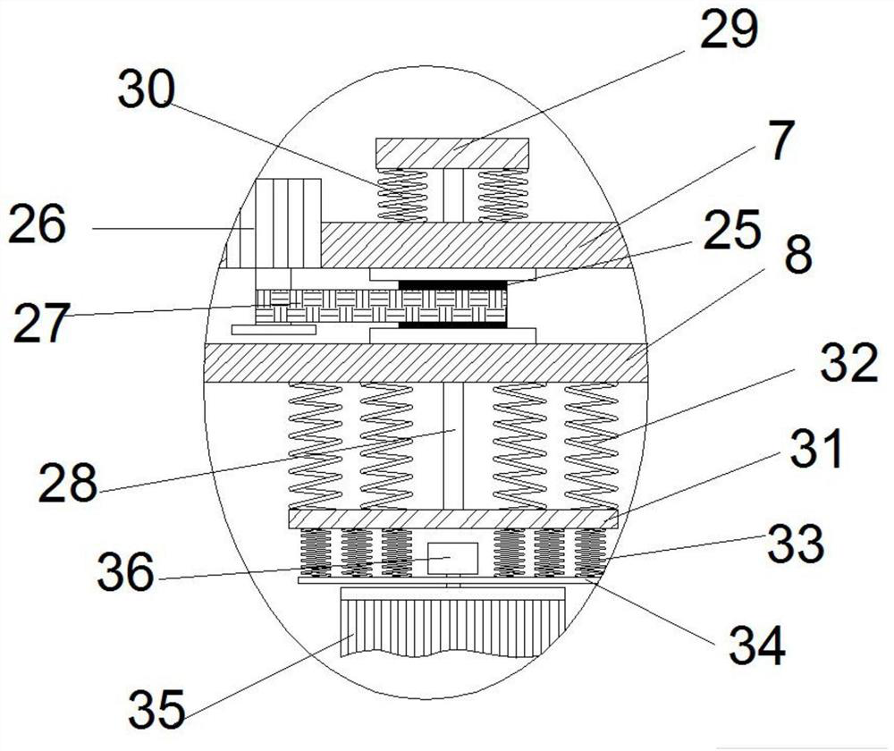
[0028] refer to Figure 1-5 , a high-stability adjustable electric industrial brush, including a workbench 1, support legs 2 arranged in a quadrangular array at the lower end of the workbench 1, side plates 3 arranged symmetrically on both sides of the upper end of the workbench 1, and a lift connected above the side plates Brush mechanism 4, first moving mechanism 5 and second moving mechanism 6, described lifting brush mechanism 4 is arranged between side plates 3, comprises upper moving rod 7, lower moving rod 8, rotating screw rod 28 and rotating brush 35, so A rotating block 25 is arranged between the upper moving rod 7 and the lower moving rod 8, and the rotating block 25 is respectively connected to the upper moving rod 7 and the lower moving rod 8 in rotation, and the upper moving rod 7 is provided with a second motor 26, and the first Two motor 26 output shafts are connected with rotating block 25 by rotating belt 27, described rotating screw rod 28 passes through upp...

Embodiment 2

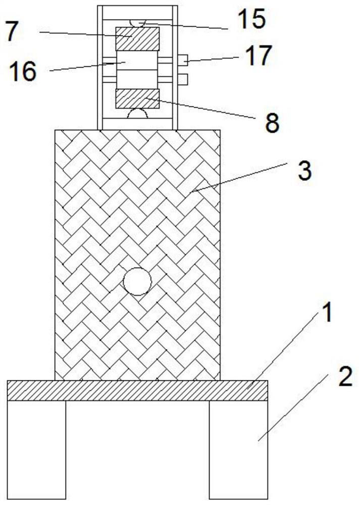
[0035] Such as Figure 1-4 and Figure 6 As shown, this embodiment is basically the same as Embodiment 1. Preferably, the upper and lower ends on the right side of the upper moving rod 7 and the lower moving rod 8 are provided with moving teeth 18, and the upper moving rod 7 and the lower moving rod 8 The top and bottom of the right fixed block 21 are provided with rotating gears 16 meshed with moving teeth 18 . The sensitivity of the left and right movement of the upper moving rod 7 and the lower moving rod 8 is effectively improved.

Embodiment 3

[0037] Such as Figure 1-6 As shown, this embodiment is basically the same as Embodiment 1. Preferably, the inside of the side plate 3 is rotatably connected to the spray port 14, and the spray port 14 communicates with the fixed water tank 13 on the upper end of the workbench 1 through a pipe. In order to facilitate cleaning and scrubbing of objects.

[0038] Working principle: when using, first fix the object to be processed on the workbench 1, and start the first motor 17 and the second motor 26 according to the type and height of the object, so that the rotating brush 35 moves up and down, left and right, and sticks to the surface of the object Then start the third motor 36 to process the surface of the object, and at the same time, the spray port 14 can be opened to spray the object during the processing, so as to efficiently process the surface of the object.


PUM


Abstract

The invention discloses a high-stability adjustable electric industrial brush, and relates to the technical field of industrial brush machining. The high-stability adjustable electric industrial brushcomprises a workbench, supporting legs, side plates, a lifting brush mechanism, a first moving mechanism and a second moving mechanism, wherein the lifting brush mechanism comprises an upper moving rod, a lower moving rod, a rotating screw rod and a rotating brush, the first moving mechanism comprises a left fixing block and two through holes formed in the upper side and the lower side of the interior of the left fixing block, the second moving mechanism comprises a right fixing block, and rotating gears inside the right fixing block, the upper moving rod and the lower moving rod penetrate through the right fixing block, moving teeth are arranged on the sides, close to each other, of the right side of the upper moving rod and the right side of the lower moving rod, and the rotating gearsmesh with the moving teeth on the upper moving rod and the moving teeth on the lower moving rod correspondingly. The high-stability adjustable electric industrial brush overcomes the defects in the prior art, is reasonable in design and convenient to use, can conveniently, effectively, uniformly and efficiently treat the surfaces of different objects, and is convenient to produce, use and adjust.

Description

technical field [0001] The invention relates to the technical field of industrial brush processing, in particular to a high-stability adjustable electric industrial brush. Background technique [0002] Industrial brushes are new types of products that are upgraded and improved on the basis of civilian brushes. They are mainly used for cleaning, dust removal, polishing, etc. in the industrial production process. Generally, they are mainly prepared as fixed devices for surface treatment of components. [0003] Traditional industrial brush equipment usually connects the brush disc or brush roller to the motor, adjusts the height of the brush according to the different objects to be processed, and then makes the brush process the surface of the object, which cannot be flexibly adjusted according to the shape of the object. To deal with irregular surfaces, it usually needs to be adjusted from time to time during use, which brings great inconvenience to specific use. Contents of...

Claims


Application Information

Patent Timeline
Patent Type & Authority Applications(China)
IPC IPC(8): B08B1/00B08B1/04B08B3/02B08B13/00
CPCB08B1/002B08B1/04B08B3/02B08B13/00
Inventor 徐华海周乾汪鲁平方润泽华凯
Owner 安徽环美刷业股份有限公司
Why Eureka
Try Eureka