Automatic-cleaning-type tea-picking storing device

An automatic cleaning and holding device technology, applied in the field of cleaning, can solve the problems of tea quality reduction, tea appearance damage, tea physical damage, etc., to achieve the effect of reducing separation work, less manual operation, and avoiding physical damage

Active Publication Date: 2020-10-30
湖北省惠愉茶业股份有限公司
View PDF12 Cites 3 Cited by
  • Summary
  • Abstract
  • Description
  • Claims
  • Application Information

AI Technical Summary

Problems solved by technology

[0003] The cleaning method that is often used now is: stirring and cleaning the tea leaves by stirring, and the method of stirring and cleaning

Method used


Image

  • Automatic-cleaning-type tea-picking storing device
  • Automatic-cleaning-type tea-picking storing device
  • Automatic-cleaning-type tea-picking storing device

Examples


Embodiment 1

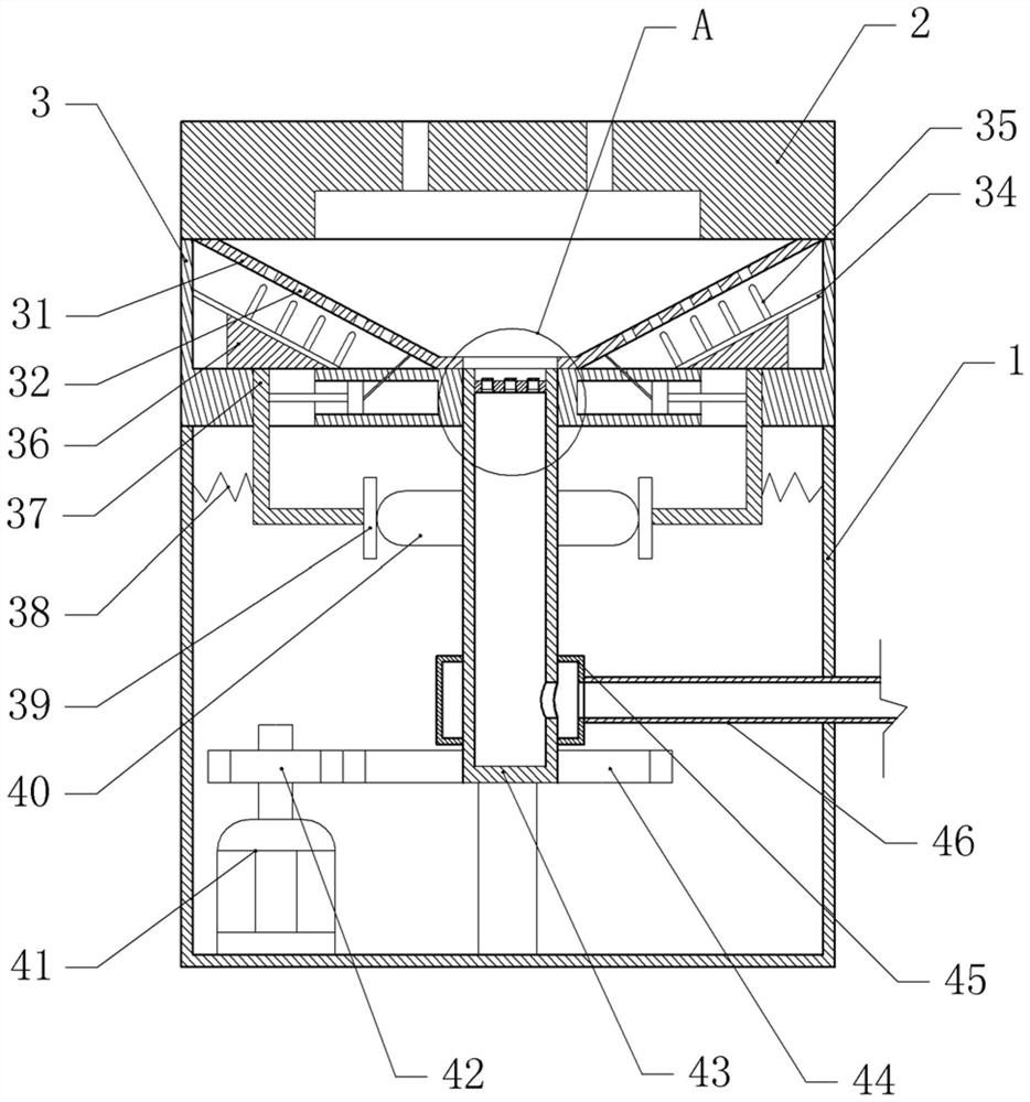
[0036] Basic as attached figure 1 , attached figure 2 And attached image 3 As shown, a self-cleaning type tea-picking storage device includes a cleaning box 3 with an upper opening, and a cover plate 2 is detachably connected to the cleaning box 3, and a pressure relief hole is opened on the cover plate 2.

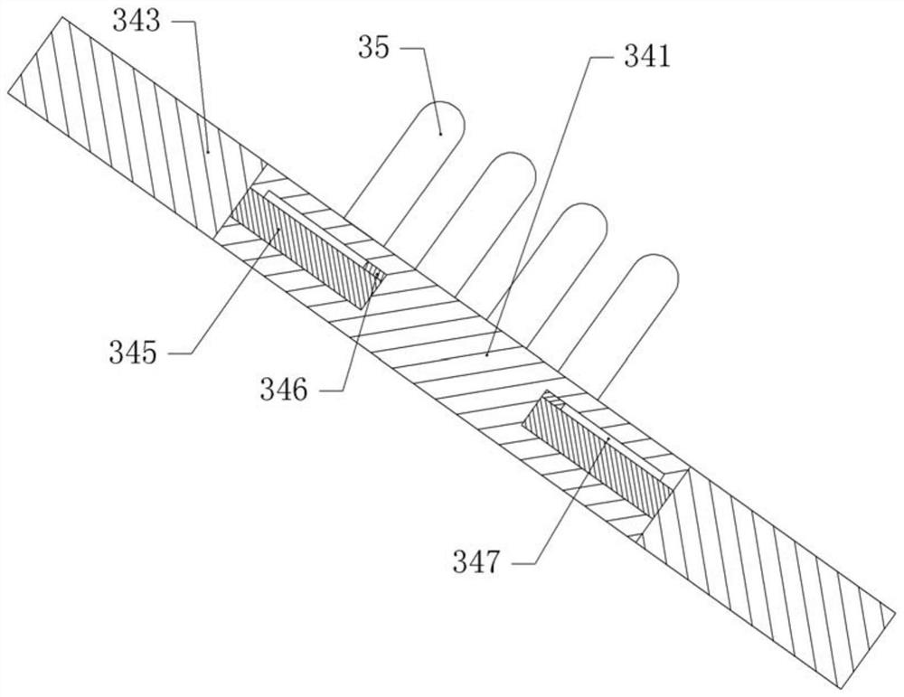
[0037] Both sides of the cleaning box 3 are bolted with a sieve plate 31, the sieve plate 31 is inclined towards the middle of the cleaning box 3, and a number of sieve holes 32 are opened on the sieve plate 31. An inclined anti-blocking plate 34 is arranged in the cavity, and the anti-blocking plate 34 and the sieve plate 31 are located on the same horizontal plane and are horizontal. The blocking shaft 35 and the anti-blocking shaft 35 can extend into the sieve hole 32 of the sieve plate 31, and the two sub-plates 343 are respectively slidably connected with the side walls of the cleaning box. A movable plate 345 slidingly connected with the movable groove 347 is fo...

Embodiment 2

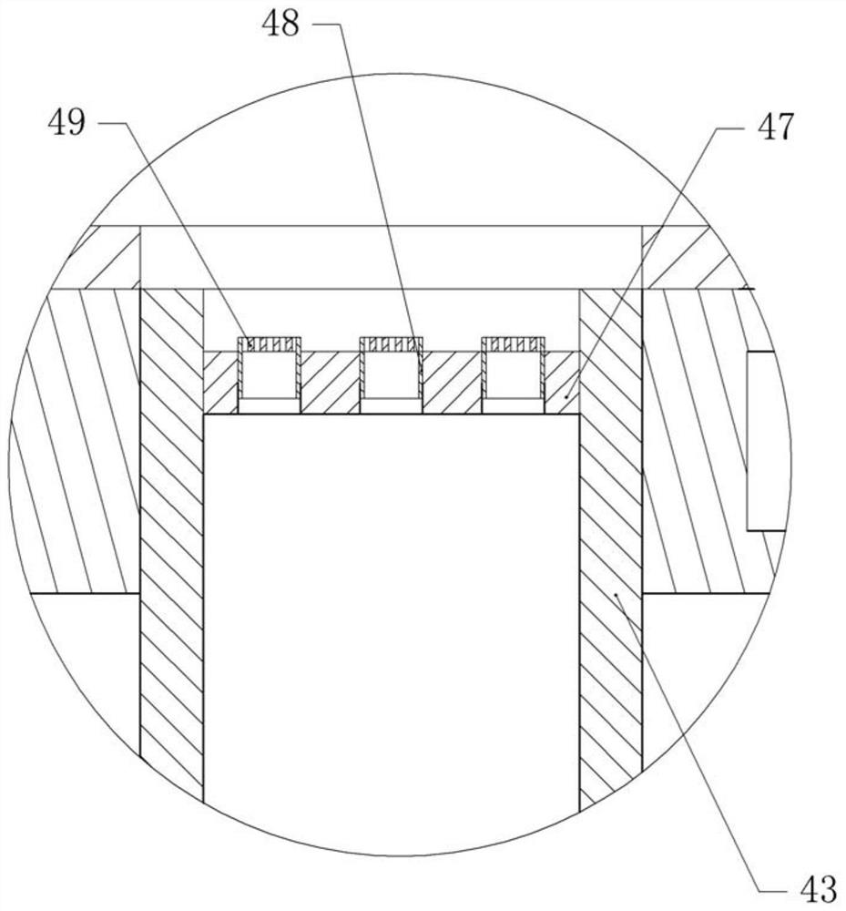
[0045] The difference between embodiment two and embodiment one is that, as attached Figure 4 And attached Figure 5 As shown, there is a water inlet hole on the cover plate 2, and the water inlet hole is connected with a water pump through a pipeline, and the cover plate 2 is rotatably connected with a stirring shaft 21 located below the water hole, and several stirring blades 22 are fixed on the stirring shaft 21 by bolts. . An air plate 52 is fixed inside the branch pipe 48, and air holes with a diameter of 1-6 mm are opened on the air plate 52, and the diameter of the air holes in this embodiment is 4 mm. The rotating shaft 43 is fixed with a blocking plate 5 by bolts, and the upper end of the branch pipe 48 is fixedly connected with the blocking plate 5 by bolts.

[0046] The specific implementation process is as follows:

[0047] The operator sends water into the cleaning box 3 through the water pump and the water hole box, and the water impacts the stirring blade 22...


PUM


Abstract

The invention relates to the technical field of cleaning, and discloses an automatic-cleaning-type tea-picking storing device. The automatic-cleaning-type tea-picking storing device comprises a cleaning tank with an upper opening, a cover plate used for closing the opening is detachably connected to the cleaning tank, and a plurality of pressure-relief openings are formed in the cover plate; the two sides in the cleaning tank are provided with sieve plates correspondingly, a plurality of sieve holes are formed in the sieve plates, and the sieve plates and the cleaning tank constitute a storagecavity; the lower parts of the sieve plates are slidably connected with anti-blocking plates, a plurality of anti-blocking shafts are arranged on the anti-blocking plates, and reciprocating pushing mechanisms are arranged below the anti-blocking plates; an equipment box is arranged below the cleaning tank, a hollow rotary shaft rotationally connected with the equipment box is arranged in the equipment box, a driving piece driving a rotary shaft is fixed into the equipment box, and the upper part of the rotary shaft communicates with a plurality of branch pipes which communicate with the cleaning tank; and gas tanks fixed to the equipment box is arranged on the outer side of the lower part of the rotary shaft in a sleeving mode, and the gas tank communicates with a gas source. The automatic-cleaning-type tea-picking storing device is simple in structure, a turbulent flow is formed through rotation of the rotary shaft to conduct impurity separation on tea leaves, and the purpose of cleaning the tea leaves is achieved.

Description

technical field [0001] The invention relates to the technical field of cleaning, in particular to an automatic cleaning type tea picking storage device. Background technique [0002] At present, tea picking is divided into mechanical picking and manual picking. Both mechanical picking and manual picking will lead to some impurities on the tea leaves. In order to ensure the quality of the tea leaves, it is necessary to clean the tea leaves to reduce the impurities contained in the tea leaves. [0003] The cleaning method that is often used now is: the tea leaves are stirred and cleaned by stirring, and the method of stirring and cleaning easily causes physical damage to the tea leaves, damages the appearance of the tea leaves, and reduces the quality of the tea leaves. In this regard, it is necessary to improve the cleaning device of tea leaves to improve the cleaning quality of tea leaves. Contents of the invention [0004] The present invention intends to provide an auto...

Claims


Application Information

Patent Timeline
IPC IPC(8): B08B3/10B08B13/00
CPCB08B3/10B08B3/102B08B13/00
Inventor 姜锐
Owner 湖北省惠愉茶业股份有限公司
Why Eureka
Try Eureka