Assembly type bridge splicing bent cap mounting method and supporting structure

An installation method and technology of supporting structure, applied in the direction of erecting/assembling bridges, bridges, bridge parts, etc., can solve problems such as high cost, failure to reflect the superiority of prefabricated bridges, and temporary support occupying ground road space, etc.

Pending Publication Date: 2020-10-30
THE FIRST ENG CO LTD OF CTCE GRP +1
View PDF0 Cites 1 Cited by
  • Summary
  • Abstract
  • Description
  • Claims
  • Application Information

AI Technical Summary

Problems solved by technology

[0004] However, the temporary support occupies the space of the road on the ground, and it cannot guarantee the passage of vehicles in the narrow section of the road; for special piers such as piers in the water where temporary supports cannot be erected on both sides, splicing cap beams cannot be installed; for high piers, corresponding measures to increase the su

Method used


Image

  • Assembly type bridge splicing bent cap mounting method and supporting structure
  • Assembly type bridge splicing bent cap mounting method and supporting structure
  • Assembly type bridge splicing bent cap mounting method and supporting structure

Examples


Embodiment 1

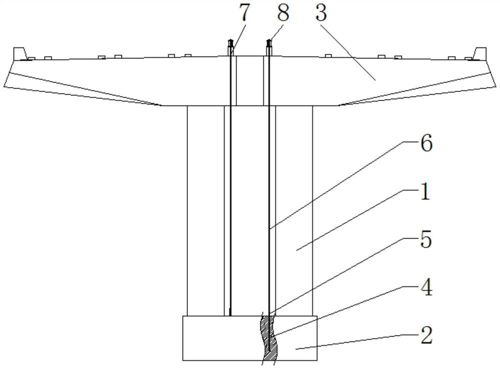
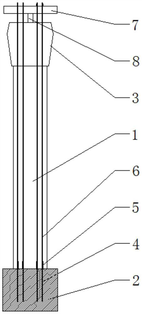
[0042] see Figure 1-2 , in an embodiment of the present invention, a prefabricated bridge splicing cover beam installation support structure includes a connecting seat fixedly connected to the cap 2, the connecting seat is a pre-embedded steel bar 4 pre-buried in the cap 2, and the pre-embedded steel bar 4 The upper end is provided with a connecting sleeve 5, the supporting rod is a load-bearing steel bar 6, and the bearing steel bar 6 is fixedly connected with the embedded steel bar 4 through the connecting sleeve 5, the upper end of the connecting seat is fixedly connected with a supporting rod, and the top end of the supporting rod is fixedly connected with a reaction frame 8 , The first jack 7 is fixedly connected to the bottom of the reaction frame 8, and the upper part of the support rod is threaded with a fastening nut, and the fastening nut is located below the reaction frame 8.

[0043] A method for installing a prefabricated bridge splicing cap beam, comprising the ...

Embodiment 2

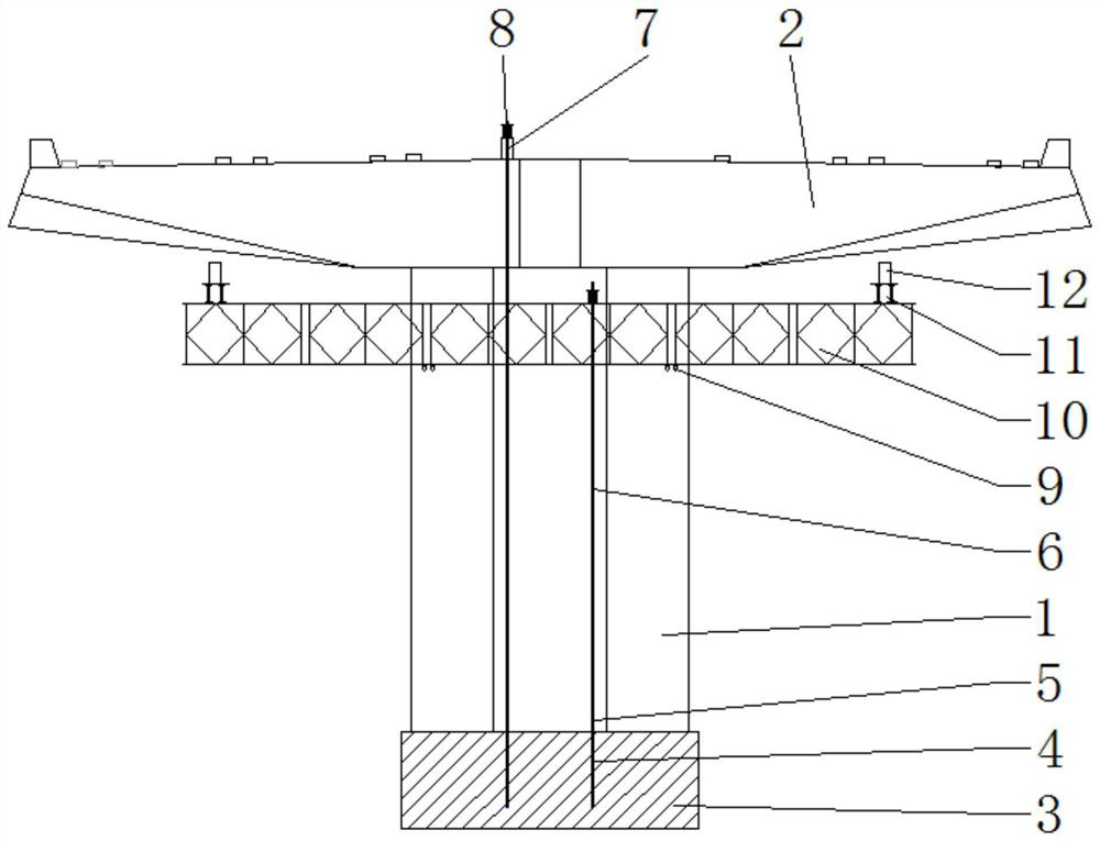
[0060] see Figure 3-4 , in an embodiment of the present invention, a prefabricated bridge splicing cover beam installation support structure includes a connecting seat fixedly connected to the cap 2, the connecting seat is a pre-embedded steel bar 4 pre-buried in the cap 2, and the pre-embedded steel bar 4 The upper end is provided with a connecting sleeve 5, the supporting rod is a load-bearing steel bar 6, and the bearing steel bar 6 is fixedly connected with the embedded steel bar 4 through the connecting sleeve 5, the upper end of the connecting seat is fixedly connected with a supporting rod, and the top end of the supporting rod is fixedly connected with a reaction frame 8 , The first jack 7 is fixedly connected to the bottom of the reaction frame 8, and the upper part of the support rod is threaded with a fastening nut, and the fastening nut is located below the reaction frame 8.

[0061] It also includes a Bailey frame 10 fixedly connected to the bridge column 1, a di...


PUM


Abstract

The invention discloses an assembly type bridge splicing bent cap mounting method and a supporting structure, and the method comprises the following steps: 1, forming at least one mounting hole in thetail of a to-be-mounting bent cap, and fixedly connecting at least one connecting base to a bearing platform below a bridge; 2, hoisting the to-be-mounted bent cap to the upper end of the bridge stand column through hoisting equipment; 3, enabling a supporting rod to penetrate through the bent cap tail mounting hole, wherein the lower end of the supporting rod is fixedly connected with the connecting base on the bearing platform, the top end of the supporting rod is fixedly connected with the bent cap tail, the hoisting tool is withdrawn, and mounting of the bent cap is completed; and 4, repeating the step 3; hoisting the other bent cap and connecting the two bent caps together through pouring so as to complete mounting of the spliced bent caps; according to the mounting method, the rearanchor type and front support rear anchor type assembly type bridge bent cap mounting technology is adopted, the site construction space is reduced, normal transportation is guaranteed, constructors and construction machines are reduced, and the safety risk in construction is also reduced.

Description

technical field [0001] The invention relates to the technical field of installation of prefabricated bridge splicing cover beams, in particular to an installation method and supporting structure of prefabricated bridge splicing cover girders. Background technique [0002] The cover beams used in prefabricated bridges with two-way six lanes or more in urban viaducts are generally more than 27m long, and most of them are long cantilever structures. Splicing type, that is, after the piers are hoisted in place separately, the middle is connected into a whole with post-wetting joints. However, due to the too long boom of the single-piece cover beam, the single-piece cover beam cannot maintain its own balance after hoisting the single-piece cover beam in sequence at the installation site. Therefore, it is necessary to install temporary supports above the center of gravity to ensure the stability of the single-piece cover beam. [0003] The linear control method of the prefabricat...

Claims


Application Information

Patent Timeline
IPC IPC(8): E01D21/00E01D19/00
CPCE01D19/00E01D21/00
Inventor 张明旭胡柱奎张杰胜刘敉密祖平廖志良贾凤贺
Owner THE FIRST ENG CO LTD OF CTCE GRP
Why Eureka
Try Eureka