
Floating garbage fishing device for sewage treatment

A sewage treatment and salvage device technology, applied in water/sewage treatment, water/sludge/sewage treatment, cleaning of open water surface, etc., can solve the problems of short service life, heavy labor, heavy net bag load, etc., to avoid The effects of salvage failure, extended use time, and large salvage area

Inactive Publication Date: 2020-10-30
刘春元
View PDF1 Cites 4 Cited by
  • Summary
  • Abstract
  • Description
  • Claims
  • Application Information

AI Technical Summary

Problems solved by technology

[0003] There are solid waste floating in part of the wastewater. At present, most of the floating waste in the waste water are separated by filtering and salvage. However, most of the existing salvage methods directly pass the sewage through the net bag, and then separate the floating waste. This separation The labor load of the method is large, and the load on the net bag is large during the separation process, and the service life is short

Method used


Image

  • Floating garbage fishing device for sewage treatment
  • Floating garbage fishing device for sewage treatment
  • Floating garbage fishing device for sewage treatment

Examples


Embodiment 1

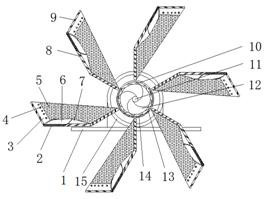
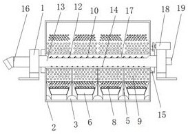
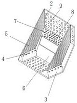
[0027] refer to Figure 1-4 , a floating garbage salvage device for sewage treatment, comprising two mounting frames 1, a conveying shell 13 is fixedly installed between the two mounting frames 1, and a discharge pipe 16 is fixedly mounted on the end of the conveying shell 13, conveying The other end of housing 13 is fixedly installed with main driving motor 19, and between the output shaft of main driving motor 19 and the interior of conveying housing 13, conveying shaft 11 is installed through bearing, and the outer side of conveying shaft 11 is fixedly installed with spiral distribution. The push paddles 12 are provided, and the top of the conveying housing 13 is provided with a strip-shaped feed slot 17. The outer side of the conveying housing 13 is fixedly equipped with two rotating rings 15, and the outer sides of the two rotating rings 15 are A plurality of ring-shaped salvage bucket mechanisms 2 are fixedly installed, and an auxiliary drive motor 18 is fixedly installe...

Embodiment 2

[0035] refer to figure 1 and Figure 3-5 , a floating garbage salvage device for sewage treatment. Compared with Embodiment 1 in this embodiment, a plurality of support rods 22 are fixedly installed on the tops of the two installation frames 1, and solar energy is fixedly installed between the top ends of the support rods 22. The solar panel 21 and the bottom of the solar panel 21 are fixedly equipped with a spray mechanism 20, and the device can provide auxiliary power supply through the solar panel 21, thereby reducing the demand for power during the operation of the device and reducing the cost of sewage treatment.

[0036] The spraying mechanism 20 comprises a spraying pipe and a spraying branch pipe which is screwed to the bottom of the side of the spraying pipe, and the spraying branching pipe is distributed obliquely, and a sewage pump is fixedly installed at the end of the spraying pipe. In the sewage treatment pool, the water in the pool is sent to the spray mechanis...


PUM


Abstract

The invention discloses a floating garbage fishing device for sewage treatment, and relates to the technical field of sewage treatment. In order to solve the problem of the large labor of an existingfloating garbage separation method, large load on a net bag during a separation process and short service life, the floating garbage fishing device comprises two installation frames, a conveying shellis fixedly installed between the two installation frames, a discharging pipe is fixedly installed at the end of the conveying shell, and a main drive motor is fixedly installed at the other end of the conveying shell. According to the invention, flotage in waste water is lifted up by a fishing bucket mechanism, when rotating upwards, the flotage falls into the inside of a feeding hole trough by action of gravity, namely, the flotage is pushed in the direction of the discharging pipe through a rotating push paddle, and the fishing and purification effects of the flotage in the sewage are achieved; and the device has a large fishing area, sustainable fishing and purification work, and the treatment efficiency of the floating garbage in a sewage treatment process is improved.

Description

technical field [0001] The invention relates to the technical field of sewage treatment, in particular to a floating garbage fishing device for sewage treatment. Background technique [0002] Sewage refers to the effluent water from domestic and production that is polluted to a certain extent. Water that has lost its original function is simply called sewage. It is mainly the water after daily use, which contains more organic matter and is easier to treat. Among the water pollution caused by human production activities, the water pollution caused by industry is the most serious. For example, industrial wastewater contains many pollutants and complex components. It is not only difficult to purify in water, but also difficult to treat. It is the most important cause of water pollution caused by industrial pollution. It accounts for the majority of pollutants emitted by industry. The pollutants contained in industrial wastewater vary widely depending on the type of factory....

Claims


Application Information

Patent Timeline
IPC IPC(8): E02B15/10C02F1/00
CPCC02F1/00E02B15/10E02B15/103E02B15/104
Inventor 刘春元
Owner 刘春元
Learn More