Driving chain structure of wind generating set and wind driven generator comprising same

A technology for wind power generators and wind power generators, which is applied in the drive chain structure and wind power generator fields, and can solve the problem of increasing size, increasing the alternating gravity moment and fatigue alternating load of fan impellers, increasing manufacturing and transportation costs, etc. problem, achieve the effect of reducing bending moment, reducing fatigue alternating load and reducing size

Inactive Publication Date: 2020-10-30
SHANGHAI ELECTRIC WIND POWER GRP CO LTD
View PDF7 Cites 2 Cited by
  • Summary
  • Abstract
  • Description
  • Claims
  • Application Information

AI Technical Summary

Problems solved by technology

[0004] The front bearing and the rear bearing of the drive chain structure of the existing wind power generating set are located on one side of the hub of the fan impeller, which not only needs to bear the bending moment of the fixed fan impeller, but also increases the distance between the front and rear bearings from the center of the hub. The alternating gravity moment and fatigue alternating load of the fan impeller it bears, so larger-sized bearings are required, which correspondingly increases the size of the main shaft, front bearing housing, and rear bearing housing, increasing manufacturing and transportation costs

Method used


Image

  • Driving chain structure of wind generating set and wind driven generator comprising same
  • Driving chain structure of wind generating set and wind driven generator comprising same
  • Driving chain structure of wind generating set and wind driven generator comprising same

Examples


Embodiment 2

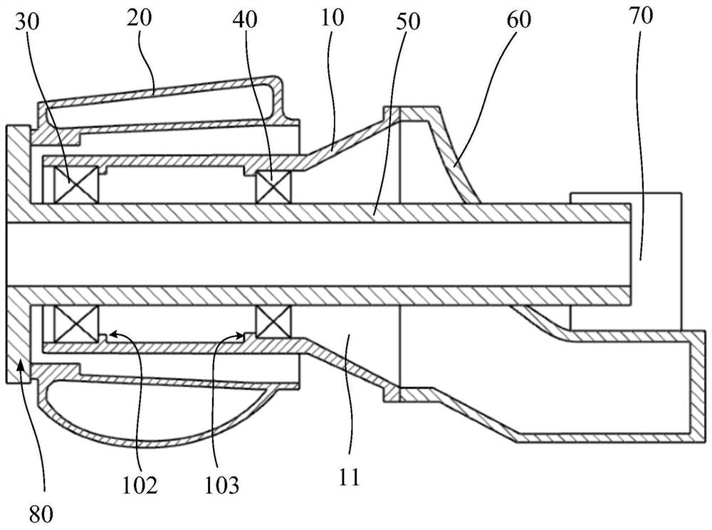
[0071] Such as image 3 As shown, the other structures of this embodiment and Embodiment 1 are substantially the same, the main difference is that: the inner ring portion of the front bearing 30 and the inner ring portion of the rear bearing 40 are both sleeved on the rotating shaft 50, and the outer ring portion of the front bearing 30 Both the outer ring portion of the portion and the rear bearing 40 are connected to the inner wall surface of the through hole 11 .

[0072] With the above structure, not only the bending moment of the fan impeller borne by the bearing is reduced, but also the alternating gravity moment of the fan impeller is shared by the bearing and the fixed shaft 10, and part of the alternating gravity moment of the fan impeller is shared by the fixed shaft 10, which can also reduce The size of the bearing reduces the production, transportation and installation costs of the bearing.

[0073] Such as image 3 As shown, in this embodiment, the inner wall su...


PUM


Abstract

The invention discloses a driving chain structure of a wind generating set and a wind driven generator comprising the same. The wind generating set comprises a front frame, a fan impeller, a rotatingshaft, a fixed shaft, a front bearing and a rear bearing, the fixed shaft is arranged on one side, facing the fan impeller, of the front frame, the fixed shaft is provided with a through hole which communicates with the interior of the front frame, the rotating shaft is arranged in the through hole, the front end of the rotating shaft extends out of the through hole and is fixedly connected with ahub of the fan impeller, and the hub is arranged outside the fixed shaft in a sleeving mode and can rotate relative to the fixed shaft; and the front bearing and the rear bearing are both arranged onthe fixed shaft or the rotating shaft, and the gravity center of the fan impeller is located between the front bearing and the rear bearing. According to the driving chain structure and the wind driven generator, the gravity center of the fan impeller is located between the front bearing and the rear bearing, the arm of force from the gravity center of the fan impeller to the two bearings is shortened, the bending moment of the fan impeller borne by the bearings is reduced, the fatigue alternating load required to be borne by the bearings is further reduced, therefore, the sizes of the bearings can be reduced, and the cost of the wind generating set can be reduced.

Description

technical field [0001] The invention relates to a driving chain structure of a wind power generating set and a wind power generator including the same. Background technique [0002] In the prior art, it is known that the drive chain of the wind power generating set transmits the rotation speed of the wind rotor to the generator through the gear box, and transmits the external load to the front frame and the tower at the same time. With the continuous development of wind power generation technology, the capacity of a single unit continues to increase, making the load level and external dimensions of wind turbines also continue to increase. Correspondingly, the cost of manufacturing, transportation and installation is getting higher and higher. Among them, the size of the bearing has a great influence on the total cost, and reducing the size of the main bearing in the drive chain of the wind turbine can effectively reduce the cost of the wind turbine. [0003] In the drive c...

Claims


Application Information

Patent Timeline
Patent Type & Authority Applications(China)
IPC IPC(8): F03D15/00F03D13/10F03D80/70
CPCF03D13/10F03D15/00F03D80/70Y02E10/72
Inventor 许梦华喻琪马文勇彭明孙振军
Owner SHANGHAI ELECTRIC WIND POWER GRP CO LTD
Why Eureka
Try Eureka