Sliding vane structure and compressor with sliding vane structure

A sliding vane and elastic mechanism technology, applied in the field of compressors, can solve the problems of reducing the volumetric efficiency of the compressor, deteriorating the overall performance of the compressor, reducing the volumetric efficiency of the compressor, etc., so as to reduce weight, reduce vibration and noise, and reduce reciprocation. The effect of inertial force

Pending Publication Date: 2020-10-30
ZHUHAI LANDA COMPRESSOR +1
View PDF0 Cites 0 Cited by
  • Summary
  • Abstract
  • Description
  • Claims
  • Application Information

AI Technical Summary

Problems solved by technology

[0004] During the operation of the compressor, the sliding vane has a large impact on the rollers, resulting in vibration and noise; at the same time, the end face of the sliding vane is an important leakage channel inside the compressor, which further reduces the volumetric efficiency of the compressor and the overall performance of the compressor. Poor; and the internal temperature of the compressor is high, which reduces the volumetric efficiency of the compressor and reduces the cooling capacity

Method used


Image

  • Sliding vane structure and compressor with sliding vane structure
  • Sliding vane structure and compressor with sliding vane structure
  • Sliding vane structure and compressor with sliding vane structure

Examples


Embodiment Construction

[0030] In order to make the purpose, technical solution and advantages of the present invention clearer, the technical solution of the present invention will be described in detail below. Apparently, the described embodiments are only some of the embodiments of the present invention, but not all of them. Based on the embodiments of the present invention, all other implementations obtained by persons of ordinary skill in the art without making creative efforts fall within the protection scope of the present invention.

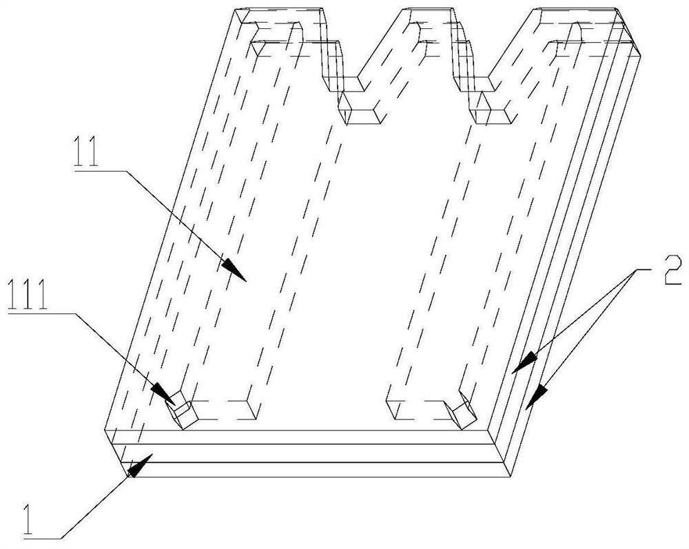
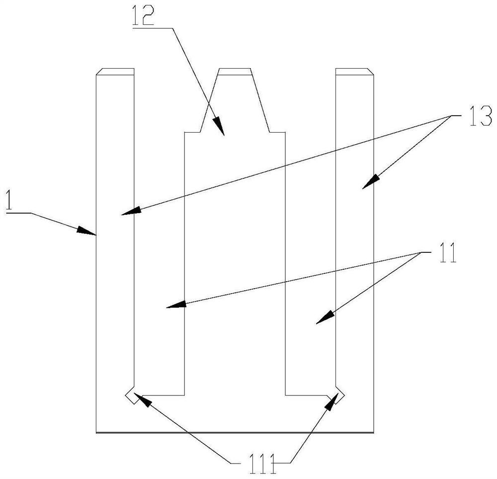
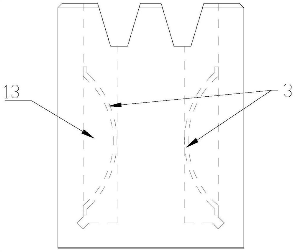
[0031] Such as Figure 1-Figure 7 As shown, the present invention provides a slider structure, including a middle slider 1 and an outer slider 2, the number of the middle slider 1 is N layers, the number of the outer sliders 2 is N+1 layers, and the outer layer The slides 2 and the middle slides 1 are arranged alternately in sequence, and N is a positive integer greater than or equal to 1; wherein, each middle slide 1 has an opening groove 11, so that the middl...


PUM

PropertyMeasurementUnit
Thicknessaaaaaaaaaa
Widthaaaaaaaaaa

Abstract

The invention provides a sliding vane structure and a compressor with the sliding vane structure, and relates to the technical field of compressors. The sliding vane structure and the compressor withthe sliding vane structure solve the technical problem that an existing sliding vane has a relatively large impact on a roller. The sliding vane structure comprises N middle-layer sliding vanes and N+1 outer-layer sliding vanes, wherein the middle-layer sliding vanes and the outer-layer sliding vanes are alternately arranged in sequence; N is a positive integer greater than or equal to 1; and eachmiddle-layer sliding vane is provided with open grooves, so that a cavity structure is formed between each middle-layer sliding vane and the corresponding two adjacent outer-layer sliding vanes. Eachmiddle-layer sliding vane is provided with the corresponding open grooves so as to reduce the weight of the sliding vanes, decrease the reciprocating inertia force in the working process, decrease the impact on the roller, and reduce vibration and noise. In addition, each cavity structure formed between the corresponding middle-layer sliding vane and the corresponding two adjacent outer-layer sliding vanes can be used for storing a certain amount of lubricating oil so as to facilitate the reduction in the internal temperature of a pump body, increase the volumetric efficiency of the compressor, increase the cooling capacity, and improve the comprehensive performance of the compressor.

Description

technical field [0001] The invention relates to the technical field of compressors, in particular to a sliding vane structure and a compressor provided with it. Background technique [0002] As an important part of the compressor, the sliding vane has a great influence on the performance of the compressor. [0003] The applicant finds that the prior art has at least the following technical problems: [0004] During the operation of the compressor, the sliding vane has a large impact on the rollers, resulting in vibration and noise; at the same time, the end face of the sliding vane is an important leakage channel inside the compressor, which further reduces the volumetric efficiency of the compressor and the overall performance of the compressor. Poor; and the internal temperature of the compressor is high, which reduces the volumetric efficiency of the compressor and reduces the cooling capacity. Contents of the invention [0005] The object of the present invention is ...

Claims


Application Information

Patent Timeline
IPC IPC(8): F04C18/356F04C29/02F04C27/02F04C29/04
CPCF04C18/356F04C29/0007
Inventor 李伟陈可余风利廖熠
Owner ZHUHAI LANDA COMPRESSOR
Why Eureka
Try Eureka