Heat exchanger fins

A technology for heat exchangers and fins, applied in heat exchange equipment, heat exchanger shells, cleaning heat transfer devices, etc., can solve the problems of base tube welding through, inconvenient cleaning of fins, and reduced heat exchange efficiency of heat exchangers

Pending Publication Date: 2020-10-30
汤宝宝
View PDF9 Cites 2 Cited by
  • Summary
  • Abstract
  • Description
  • Claims
  • Application Information

AI Technical Summary

Problems solved by technology

[0003] However, the fins of the existing box-type heat exchangers are mostly directly welded on the base pipe of the box-type heat pipe, which is cumbersome, and the base pipe is easy to be welded through if you do not pay attention during welding, and the existing box-type hea

Method used


Image

  • Heat exchanger fins
  • Heat exchanger fins
  • Heat exchanger fins

Examples


Embodiment Construction

[0025] In order to make the purpose, features and advantages of the present invention more obvious and understandable, the technical solutions in the embodiments of the present invention will be clearly and completely described below in conjunction with the accompanying drawings in the embodiments of the present invention. Obviously, the following The described embodiments are only some, not all, embodiments of the present invention. Based on the embodiments of the present invention, all other embodiments obtained by persons of ordinary skill in the art without making creative efforts belong to the protection scope of the present invention.

[0026] The technical solutions of the present invention will be further described below in conjunction with the accompanying drawings and through specific implementation methods.

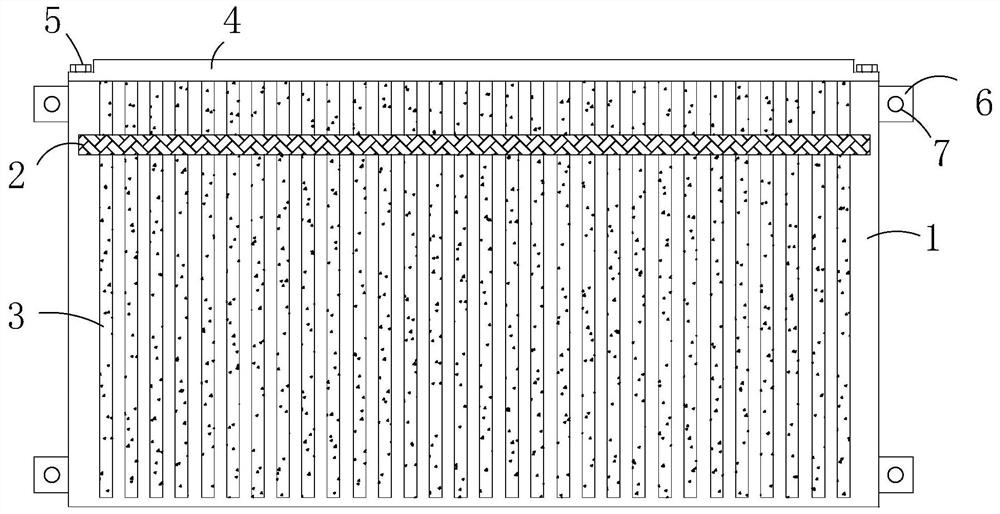
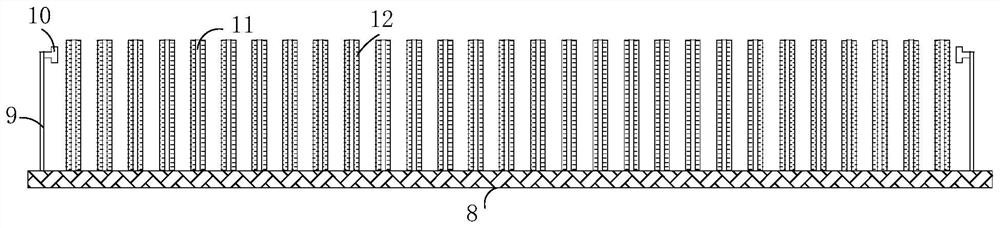
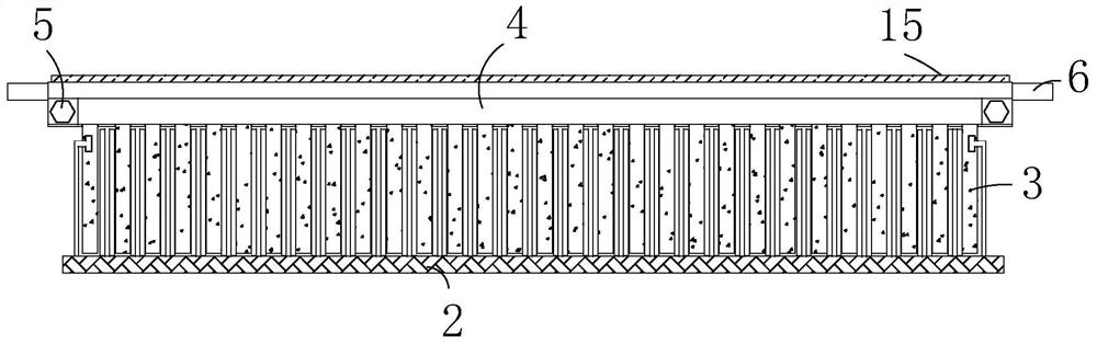
[0027] see Figure 1-5 As shown, a heat exchanger fin includes a fin plate 1, a soot wiping mechanism 2, and a fin 3. One side of the fin plate 1 is evenly an...


PUM

PropertyMeasurementUnit
Thicknessaaaaaaaaaa
Thicknessaaaaaaaaaa

Abstract

The invention relates to the field of fins, in particular to heat exchanger fins. The heat exchanger fins involve a fin plate, a dust wiping mechanism, fin bodies, a sealing plate, bolts, mounting lugs, mounting holes, a dust wiping plate mounting plate, a positioning sliding plate, a sliding block, a dust wiping plate, a brush, a sliding groove, a threaded hole, a strip-shaped sliding block and aheat conduction film. The heat exchanger fins involve the fin plate, the fin bodies are installed on the fin plate in a sliding mode, after the fin bodies are installed, only the fin plate needs to be installed on the outer wall of a box-type base tube, welding is not needed, the situation that the base tube is welded in a penetrating mode when the fin bodies are welded is avoided, and installation of the fin bodies is greatly facilitated; and when the dust wiping mechanism slides, the brush on the dust wiping plate of the dust wiping mechanism wipes off dust on the outer walls of the fin bodies, cleaning of dust adhering to the outer walls of the fin bodies is facilitated, cleaning of the device is greatly facilitated, the situation that the heat exchange efficiency is reduced due to thefact that the dust adhere to the fin bodies is greatly reduced, and the heat exchange efficiency of the device is guaranteed.

Description

technical field [0001] The invention relates to the field of fins, in particular to a heat exchanger fin. Background technique [0002] Fin heat exchanger is a kind of heat exchanger, which is the most widely used heat exchange equipment in gas and liquid heat exchangers. Fin heat exchangers can be divided into box heat exchangers and tube heat exchangers. , no matter what kind of fin heat exchanger achieves the purpose of enhancing heat transfer by adding fins to the ordinary base tube, the fins can also use steel strips, stainless steel strips, copper strips, aluminum strips, etc., among which the box type The heat exchanger is one of the more common heat exchangers. [0003] However, the fins of the existing box-type heat exchangers are mostly directly welded on the base pipe of the box-type heat pipe, which is cumbersome, and the base pipe is easy to be welded through if you do not pay attention during welding, and the existing box-type heat pipe It is inconvenient to ...

Claims


Application Information

Patent Timeline
IPC IPC(8): F28F3/06F28F9/26F28G1/02
CPCF28F3/06F28F9/262F28G1/02
Inventor 汤宝宝焦阳
Owner 汤宝宝
Why Eureka
Try Eureka