Check patentability & draft patents in minutes with Patsnap Eureka AI!

Motor rotation detection device

A technology of rotation detection and photoelectric detection, which is applied in the direction of measuring device, measuring device casing, motor generator test, etc., can solve problems such as visual fatigue, visual misjudgment of inspectors, and difficulty in guaranteeing the detection effect and efficiency of manual visual observation and judgment, etc. To achieve the effect of guaranteed effect and efficiency

Pending Publication Date: 2020-10-30
CHANGSHA GREE HVAC EQUIP CO LTD +1
View PDF0 Cites 0 Cited by
  • Summary
  • Abstract
  • Description
  • Claims
  • Application Information

AI Technical Summary

Problems solved by technology

The existing problem is that the visual observation of the rotating blades and direction indicators requires a certain length of observation, which is likely to cause visual fatigue. At the same time, in the static state, the indication effect of the direction indicators is obvious, but in the rotating state In this case, the inspector may have visual misjudgment
The problems pointed out above make it difficult to guarantee the detection effect and efficiency of manual visual observation and judgment

Method used


Image

  • Motor rotation detection device
  • Motor rotation detection device
  • Motor rotation detection device

Examples


Embodiment Construction

[0028] In order to make the purpose, technical solution and advantages of the present application clearer, the technical solution of the present application will be described in detail below. Apparently, the described embodiments are only some of the embodiments of this application, not all of them. Based on the embodiments in the present application, all other implementation manners obtained by persons of ordinary skill in the art without creative efforts fall within the protection scope of the present application.

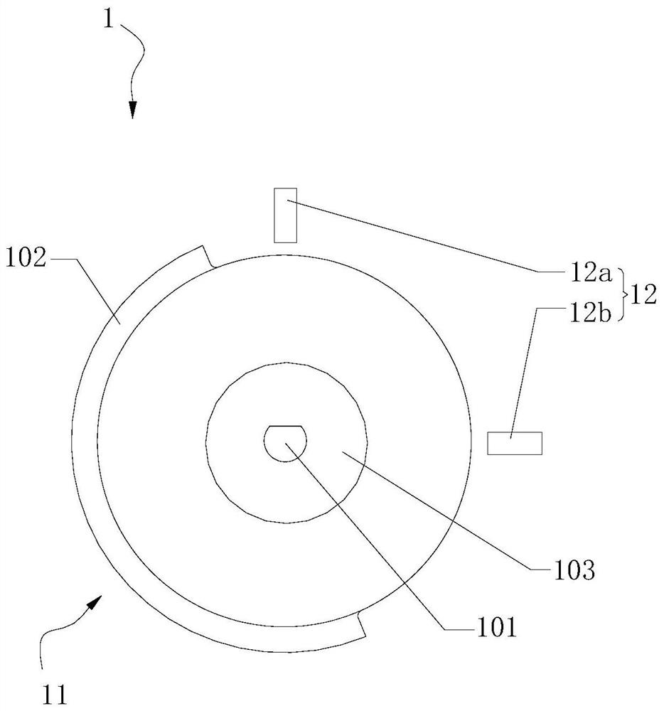
[0029] figure 1 is a schematic structural diagram of a motor rotation detection device according to an exemplary embodiment, as shown in figure 1 As shown, the motor rotation detection device 1 includes:

[0030] The rotating mechanism 11 has a central shaft hole 101 to be installed in cooperation with the motor shaft, and the rotating mechanism 11 has an arc-shaped protrusion 102 in the direction of the axial plane;

[0031] Two or more photodetection element...


PUM


Abstract

The application relates to a motor rotation detection device, which belongs to the technical field of motor detection. The device comprises a rotation mechanism and two or more than two photoelectricdetection elements. The rotation mechanism having a central shaft hole is cooperatively installed with a motor shaft, and has an arc-shaped protruding portion in the axial plane direction. The two ormore than two photoelectric detection elements are configured as follows: the photoelectric detection elements are distributed around the rotation mechanism; when the motor drives the rotation mechanism to rotate, the arc-shaped protruding part can pass through the space between a transmitting part and a receiving part of each photoelectric detection element so as to be sequentially detected by the photoelectric detection elements, and binary codes formed by signals output by the photoelectric detection elements at the same time change periodically. According to the invention, a manual visualobservation and judgment mode is replaced, and the effect and efficiency of motor rotation detection can be ensured.

Description

technical field [0001] The application belongs to the technical field of motor detection, and in particular relates to a motor rotation detection device. Background technique [0002] In related technologies for motor rotation detection, for example, the motor is judged by installing fan blades and direction indicators (eg, arrow indicators), etc., supplemented by manual visual observation of rotating fan blades and direction indicators. The existing problem is that the visual observation of the rotating blades and direction indicators requires a certain length of observation, which is likely to cause visual fatigue. At the same time, in the static state, the indication effect of the direction indicators is obvious, but in the rotating state Under the circumstances, it may cause visual misjudgment by the inspectors. The problems pointed out above make it difficult to guarantee the detection effect and efficiency of manual visual observation and judgment. Contents of the i...

Claims


Application Information

Patent Timeline
Patent Type & Authority Applications(China)
IPC IPC(8): G01R31/34G01R1/04G01P3/36G01P13/02
CPCG01R31/34G01R1/0408G01P3/36G01P13/02
Inventor 贺建王晓彬古湘龙侯华金杨通海陈鑫孙长发曹健李祥胜
Owner CHANGSHA GREE HVAC EQUIP CO LTD
Features
  • R&D
  • Intellectual Property
  • Life Sciences
  • Materials
  • Tech Scout
  • Unparalleled Data Quality
  • Higher Quality Content
  • 60% Fewer Hallucinations
Learn More