Dynamic scanning light source module and partition scanning dynamic lighting method

A light source module, dynamic scanning technology, applied in lasers, laser parts, semiconductor lasers, etc., can solve the problem of high power consumption of TOF modules

Pending Publication Date: 2020-10-30
宁波舜宇奥来技术有限公司
View PDF0 Cites 0 Cited by
  • Summary
  • Abstract
  • Description
  • Claims
  • Application Information

AI Technical Summary

Problems solved by technology

[0004] The main purpose of the present invention is to provide a dynamic scanning light source module and a parti...

Method used


Image

  • Dynamic scanning light source module and partition scanning dynamic lighting method
  • Dynamic scanning light source module and partition scanning dynamic lighting method
  • Dynamic scanning light source module and partition scanning dynamic lighting method

Examples


Embodiment 1

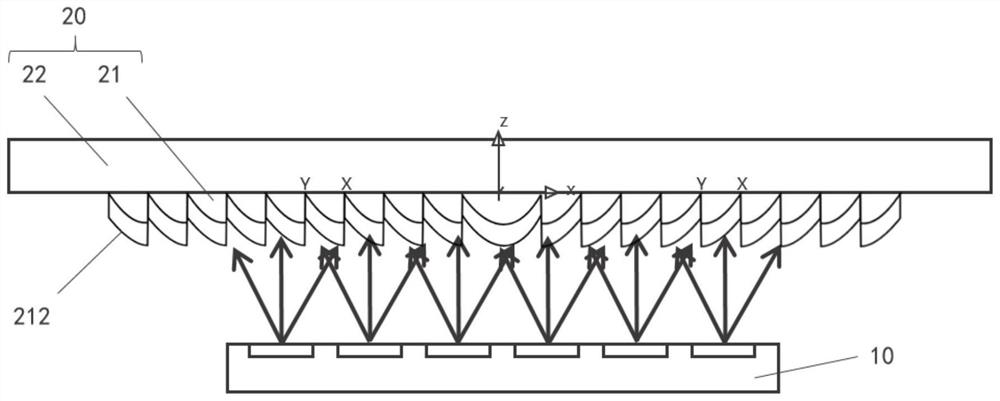
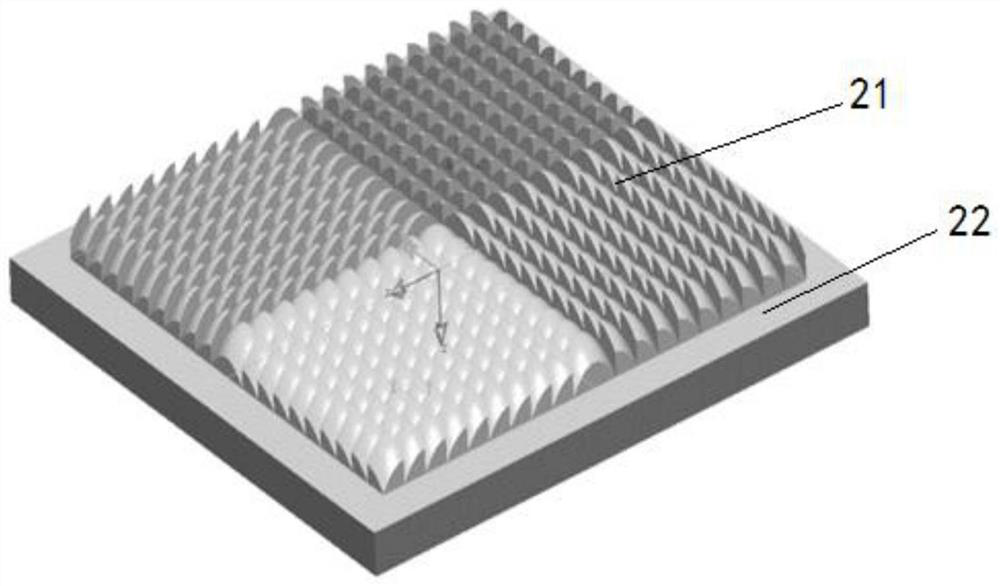
[0040] Such as Figure 1 to Figure 9 In the specific embodiment shown, the microlens array 21 includes a plurality of microlenses 211, two adjacent microlenses 211 are connected and smoothly transitioned, and the surfaces of all the microlenses 211 are connected to form a diffusion surface 212. Two adjacent microlenses 211 are connected and smoothly transitioned. The surfaces of all microlenses 211 are connected to form a diffusion surface 212. This arrangement makes the two adjacent microlenses 211 seamlessly connected to prevent the adjacent two The gap between the microlenses 211 causes light leakage, which affects the energy distribution of the spot on the detection surface, and further affects the imaging quality of the system.

[0041] It should be noted that the above-mentioned microlens array 21 is arranged periodically or randomly. The periodic arrangement is a regular and repetitive arrangement, and the structure design is simple, so that the boundary distribution of th...

Embodiment 2

[0067] The difference from the first embodiment is that the arrangement of the microlenses 211 is different. specific,

[0068] Such as Figure 10 to Figure 12 In the specific embodiment shown, the arrangement of the microlenses 211 is an arrangement in which the surface normal of the microlenses 211 diverges outward.

Embodiment 3

[0070] The difference from the first embodiment is that the partitioning mode of the microlens array is different.

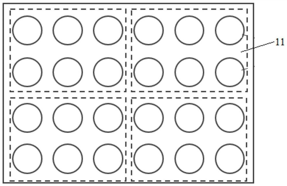
[0071] Such as Figure 13 As shown, the microlens array is divided into multiple light-transmitting areas, and the position, shape and size of the multiple light-transmitting areas can be the same or different.


PUM

PropertyMeasurementUnit
Lengthaaaaaaaaaa
Lengthaaaaaaaaaa
Thicknessaaaaaaaaaa

Abstract

The invention provides a dynamic scanning light source module and a partition scanning dynamic lighting method. The dynamic scanning light source module comprises a Vcsel light source and a diffuser.The Vcsel light source comprises a plurality of light-emitting areas, and each light-emitting area can emit light independently. The diffuser comprises a micro-lens array, the micro-lens array comprises a plurality of light-transmitting areas, the light-transmitting areas and the light-emitting areas are arranged in a one-to-one correspondence mode, and the correspondingly-arranged light-transmitting areas and the light-emitting areas are the same in shape. According to the invention, the problem of high power consumption of the TOF module in the prior art is solved.

Description

Technical field [0001] The invention relates to the technical field of optical imaging equipment, in particular to a dynamic scanning light source module and a partition scanning dynamic lighting method. Background technique [0002] At present, the main ways to realize 3D imaging in the industry are binocular, structured light and TOF. Among them, the accuracy of binocular is low, and the structure of structured light is complex and costly. However, TOF has sufficient accuracy and lower cost, and it has been popular and popularized. TOF usually consists of a transmitting end and a receiving end, and the transmitting end is mainly composed of a vcsel light source and a light diffuser. The lighting method of the existing TOF module transmitter end is mainly: all the light-emitting points are illuminated at the same time to illuminate the microlens array of the entire light diffuser, and after refraction and diffusion, illuminate the target surface, so that the entire receiving end...

Claims


Application Information

Patent Timeline
IPC IPC(8): G01S17/894G01S7/481G01S7/4911G01S7/484H01S5/00H01S5/42
CPCG01S7/4814G01S7/4817G01S7/484G01S7/4911G01S17/894H01S5/0071H01S5/423
Inventor 明玉生吴沣原魏明贵熊羚鹤孙理斌陈远
Owner 宁波舜宇奥来技术有限公司
Why Eureka
Try Eureka