Antenna structure for improving cross polarization performance of dual-polarized microstrip antenna

A microstrip antenna, cross-polarization technology, applied in the direction of the antenna grounding switch structure connection, antenna coupling, radiating element structure, etc., can solve the problems of mutual crosstalk isolation, low antenna polarization purity, and insufficient Gains, ease of debugging and real-time tuning, effects to improve cross-polar performance

Active Publication Date: 2020-10-30
SHANGHAI XUANYA TECH CO LTD
View PDF13 Cites 0 Cited by
  • Summary
  • Abstract
  • Description
  • Claims
  • Application Information

AI Technical Summary

Problems solved by technology

For microstrip antennas, cross polarization itself is a difficult point, especially for dual-polarized antennas, the microstrip feeders of the two polarization channels are connected to the same square metal patch, resulting in low polarization purity of the antenna and mutual Issues such as crosstalk and insufficient isolation

Method used


Image

  • Antenna structure for improving cross polarization performance of dual-polarized microstrip antenna
  • Antenna structure for improving cross polarization performance of dual-polarized microstrip antenna
  • Antenna structure for improving cross polarization performance of dual-polarized microstrip antenna

Examples


Embodiment 1

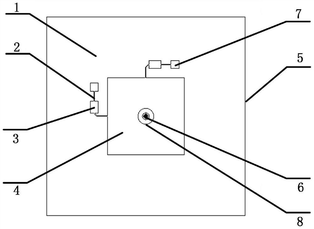
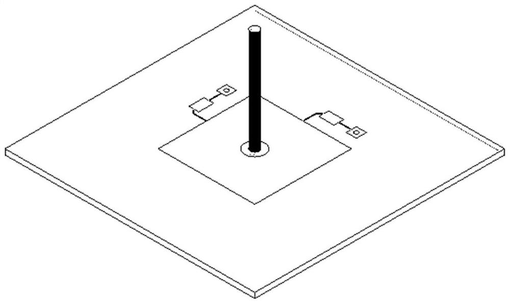
[0024] see Figure 1~5 , the present invention provides a technical solution: an antenna structure for improving the cross-polarization performance of a dual-polarized microstrip antenna, including a microwave dielectric substrate 1, a microstrip feeder 2, a distribution branch 3, a square metal patch 4, and a metal floor 5. The metal cylinder 6 and the feeding probe 7, the microstrip feeder 2, the deployment branch 3, and the square metal patch 4 are arranged on the upper surface of the microwave dielectric substrate 1, and the metal floor 5 is arranged on the microwave dielectric substrate 1 The lower surface of the distribution branch 3 and the feeding probe 7 are provided with two groups, the distribution branch 3 is connected to the square metal patch 4, and the feeding probe 7 is connected to the distribution through the microstrip feeder 2 Branches 3 are connected.

[0025] The center of the square metal patch 4 is provided with a through hole 8, the through hole 8 is ...

Embodiment 2

[0032] The difference from the first embodiment is that the metal cylinder 6 is fixedly installed on the metal floor 5 through lock nuts.

Embodiment 3

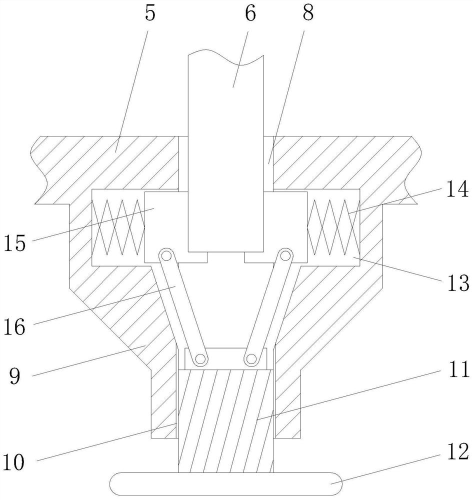
[0034] The difference from Embodiment 1 is that the metal cylinder 6 is fixed on the metal floor 5 through the installation mechanism, and the installation mechanism includes a fixing cylinder 9, which is arranged at the bottom end of the metal floor 5, and the fixing cylinder 9 The bottom end is provided with a threaded hole 10, a screw 11 is installed in the threaded hole 10, a knob 12 is installed at the bottom of the screw 11, a rotating block is connected to the top, and several connecting rods 16 are installed on the top of the rotating block. The inside of the fixed cylinder 9 is provided with a plurality of chute 13, a plurality of chute 13 is evenly distributed around the central axis of the fixed cylinder 9, a locking block 15 is slidably installed in the chute 13, and the locking block 15 is far away from the fixed One end of the central axis of the barrel 9 is connected to the inner wall of the chute 13 through a spring 14, and the top of the connecting rod 16 is co...


PUM


Abstract

The invention discloses an antenna structure for improving the cross polarization performance of a dual-polarization microstrip antenna. The antenna structure comprises a microwave dielectric substrate, a microstrip feeder line, two allocation branches, a square metal patch, a metal floor, a metal cylinder and two feed probes, wherein the microstrip feeder line, the allocation branches and the square metal patch are arranged on the upper surface of the microwave dielectric substrate; and the metal floor is arranged on the lower surface of the microwave dielectric substrate. According to the dual-polarized microstrip antenna, the cross polarization performance of the antenna can be improved only by forming a hole in the center of an original dual-polarized antenna metal patch and then installing the metal cylinder, the improvement effect is the same for two channels, and meanwhile the gain of the dual-polarized microstrip antenna is increased; the cross polarization characteristic can be adjusted by adjusting the radius and the height of the metal cylinder, and due to the fact that the metal cylinder is detachable, debugging and real-time adjustment of actual products are facilitated.

Description

technical field [0001] The invention relates to the technical field of antennas, in particular to an antenna structure for improving cross-polarization performance of a dual-polarized microstrip antenna. Background technique [0002] With the development of mobile communication technology, MIMO (Multiple-Input Multiple-output) multi-antenna technology has become a key technology for Wi-Fi and TD-LTE communication to improve communication quality and efficiency. Using dual-polarized antenna technology to achieve polarization diversity enables polarized multiple access communication to improve channel throughput and utilization. This requires the antenna unit to have excellent cross-polarization performance, otherwise the severe cross-polarization level will cause the signal of the cross-polarization channel to affect the main polarization channel, thereby affecting the selection of the channel and the transmission and reception of data information. [0003] Electromagnetic w...

Claims


Application Information

Patent Timeline
Patent Type & Authority Applications(China)
IPC IPC(8): H01Q1/38H01Q1/50H01Q1/52
CPCH01Q1/38H01Q1/50H01Q1/52
Inventor 刘中华
Owner SHANGHAI XUANYA TECH CO LTD
Why Eureka
Try Eureka