Dustproof heat dissipation type reversing camera

A camera and heat-dissipating technology, which is applied in the field of dust-proof and heat-dissipating reversing cameras. It can solve the problem that the reversing camera is easily covered by dust and the temperature, so as to achieve a good heat dissipation effect and delay the time of dust clogging.

Active Publication Date: 2020-10-30
深圳市倍特科电子有限公司
View PDF5 Cites 8 Cited by
  • Summary
  • Abstract
  • Description
  • Claims
  • Application Information

AI Technical Summary

Problems solved by technology

[0005] The purpose of the present invention is to provide a dust-proof and heat-dissipating reversing camera that can automatically remove dust and cool down to solve the problem that the above-mentioned reversing camera is easily covered by dust and has a high temperature during operation.

Method used


Image

  • Dustproof heat dissipation type reversing camera
  • Dustproof heat dissipation type reversing camera
  • Dustproof heat dissipation type reversing camera

Examples


Embodiment 1

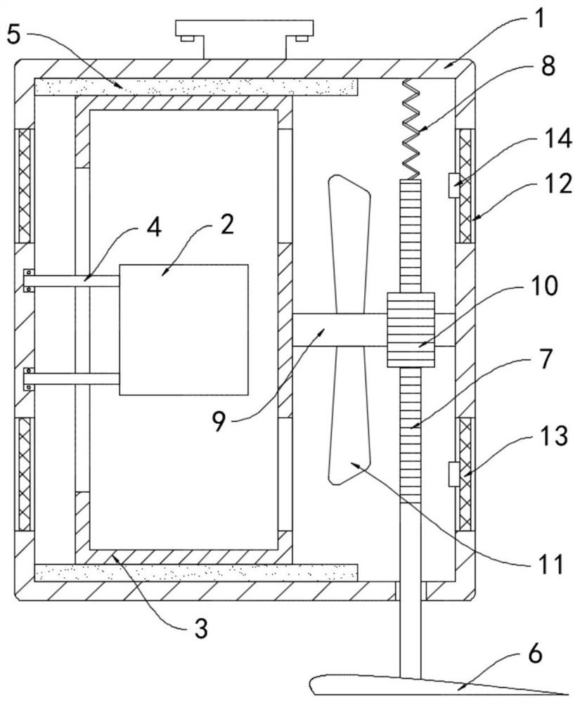
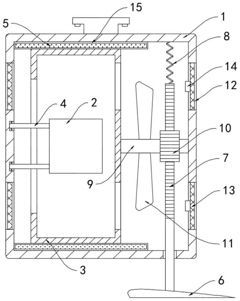
[0021] Such as Figure 1-2 As shown, a dust-proof and heat-dissipating reversing camera includes a housing 1 and a camera 2 fixedly installed at the bottom of the vehicle. A protective cover 3 is rotatably connected to the housing 1. The protective cover 3 is a transparent glass cover, and the protective cover 3 is a tube. The front end of the protective cover 3 extends out of the housing 1, and the camera 2 is installed in the protective cover 3. The camera 2 is rotationally connected with the inner side wall of the housing 1 through the connecting rod 4, and the inner side wall of the housing 1 is fixedly connected with a sticker Combine the dust removal brush 5 that protective cover 3 surface is provided with.

[0022] The bottom of the housing 1 is provided with a horizontally arranged wing plate 6, the upper surface of the wing plate 6 is in the shape of an upwardly convex arc, and the lower surface is in a horizontal line. The upper end of the wing plate 6 is fixedly con...

Embodiment 2

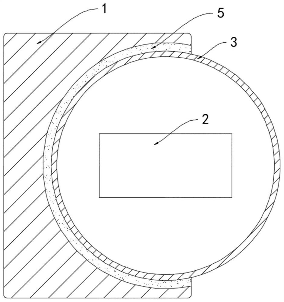
[0028] Such as image 3 As shown, the difference between this embodiment and Embodiment 1 is that the dust removal brush 5 includes a transparent liquid bag 15 fixedly connected to the inner side wall of the housing 1, and bristles are embedded on the side wall of the transparent liquid bag 15 close to the protective cover 3 , the transparent liquid capsule 15 is filled with flowing liquid mixed with magnetic powder.

[0029] In this embodiment, in the natural state, the magnetic powder in the transparent liquid capsule 15 is attracted to the side close to the wind wheel 11. After a long time of use, dust will inevitably enter the inside of the housing 1, and the dust will adhere to the surface of the wind wheel 11. As the accumulation of dust increases, the attraction force of the wind wheel 11 to the magnetic powder gradually decreases, and the magnetic powder is dispersed throughout the flow liquid. By observing the distribution of the internal magnetic powder through the t...


PUM


Abstract

The invention belongs to the field of automobile parts and relates to a dustproof heat dissipation type reversing camera. The camera comprises a shell and a camera which are fixedly mounted at the bottom of a vehicle; a protective cover is rotationally connected into the shell; the protective cover is arranged in a barrel shape; the front end of the protective cover extends out of the shell; the camera is mounted in the protective cover; the camera is rotationally connected with the inner side wall of the shell through a connecting rod; the inner side wall of the shell is fixedly connected with a dust removal brush attached to the surface of the protective cover; a horizontally-arranged wing plate is arranged below the shell; the upper surface of the wing plate is in an upwards-protrudingarc shape; the lower surface of the wing plate is in a horizontal line shape; a rack is fixedly connected to the upper end of the wing plate; and the upper end of the rack extends into the shell and is fixedly connected with the inner top face of the shell through a spring. Dust on the surface of the protective cover can be automatically brushed away, normal shooting of the camera is guaranteed, meanwhile, the cooling and heat dissipation speed of the camera can be increased, and the service life reduction caused by high temperature is avoided.

Description

technical field [0001] The invention belongs to the field of auto parts, in particular to a dust-proof and heat-dissipating reversing camera. Background technique [0002] The reversing camera and the display screen installed in the car are combined to form a complete reversing image system, which is used to observe the real-time situation behind the car when reversing, avoiding collisions and causing economic losses, especially for inexperienced drivers. convenient. [0003] Most of the existing reversing cameras are directly installed at the bottom of the rear of the car. However, when driving, the wheels rotate to drive the dust on the road surface, and there is a lot of dust floating behind the car. The dust is easy to adhere to the surface of the reversing camera, affecting its normal shooting. As a result, the display screen is blurred, the driver cannot clearly observe the situation behind the car, and it is easy to cause traffic safety accidents. When the vehicle is...

Claims


Application Information

Patent Timeline
Patent Type & Authority Applications(China)
IPC IPC(8): H04N5/225B08B1/00B08B1/02B08B13/00B60R11/04B60S1/56
CPCB08B1/002B08B1/02B08B13/00B60R11/04B60S1/566H04N23/51H04N23/50
Inventor 殷广林陈晶
Owner 深圳市倍特科电子有限公司
Why Eureka
Try Eureka