
Camera mirror surface processing system and processing method

A mirror surface processing and camera technology, which is applied in the field of camera mirror surface processing system, can solve the problems of dust and fog, affecting the shooting quality, etc., and achieve the effect of increasing the temperature

Active Publication Date: 2021-11-05
浙江翔路科技有限公司
View PDF7 Cites 0 Cited by
  • Summary
  • Abstract
  • Description
  • Claims
  • Application Information

AI Technical Summary

Problems solved by technology

[0003] The present invention proposes a camera mirror surface processing system and processing method, aiming to solve the problem that dust and fog will be attached to the mirror surface of the monitoring camera in the traditional technology and affect the shooting quality

Method used


Image

  • Camera mirror surface processing system and processing method
  • Camera mirror surface processing system and processing method
  • Camera mirror surface processing system and processing method

Examples


Embodiment Construction

[0030] The following will clearly and completely describe the technical solutions in the embodiments of the present invention with reference to the accompanying drawings in the embodiments of the present invention. Obviously, the described embodiments are only some, not all, embodiments of the present invention.

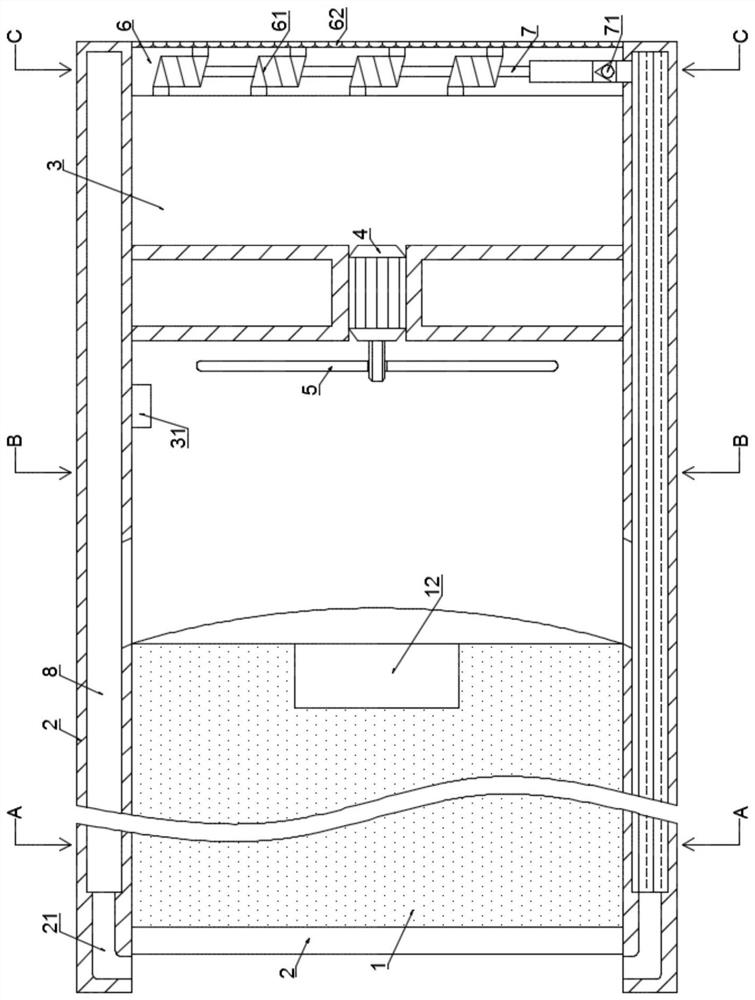
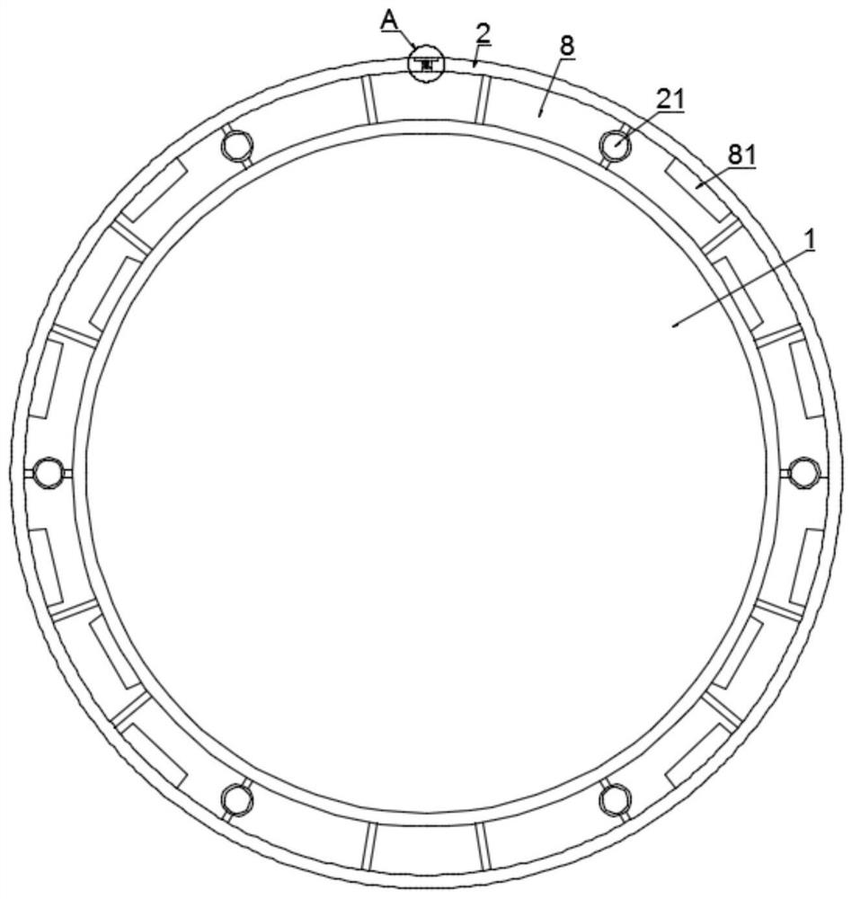
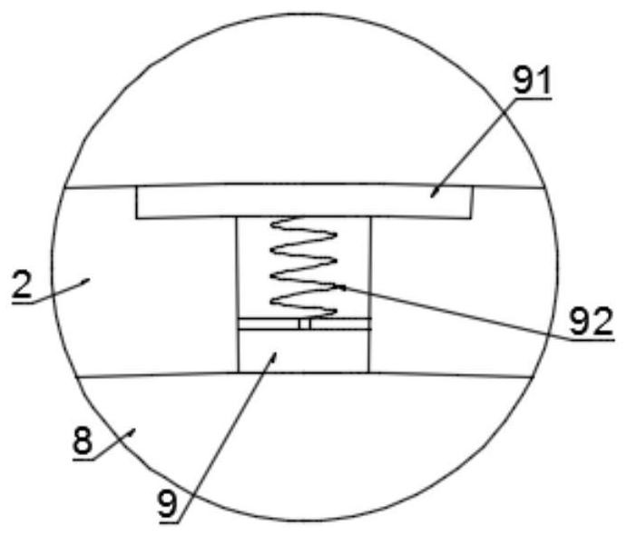
[0031] refer to Figure 1-6 , a camera mirror processing system, including a camera body 1 and a housing 2, the camera body 1 is installed in the front end of the housing 2 and a lens 101 is installed at the input end, and the camera body 1 collects camera data through the lens 101.

[0032] A processing chamber 3 is arranged at the end of the housing 2 far away from the camera body 1, and a plurality of air ducts 21 are fixedly connected to the wall of the housing 2, and the plurality of air ducts 21 are all coiled in the housing 2 to increase the contact area between the air ducts 21 and the housing 2. Improve its internal air flow stroke, increase the heat exchang...


PUM


Abstract

The invention discloses a camera mirror surface processing system, which relates to the technical field of traffic monitoring devices, and comprises a camera body and a casing. There is a processing chamber, and a plurality of air ducts are fixedly connected to the shell wall, wherein the air inlet of the air duct is connected to the processing chamber and the air outlet points to the outer surface of the lens. The processing chamber is fixedly connected with a micro motor through a bracket. The present invention continues During the working process, if there is dust and water mist attached to the surface of the lens, the natural cleaning module of the processor will work to control the normal operation of the micro motor. The spiral tube enters the processing room, and blows to the mirror surface from the air outlet of the air tube, removes the dust and water mist on it, and restores the camera effect of the camera body.

Description

technical field [0001] The invention relates to the technical field of traffic monitoring devices, in particular to a camera mirror processing system and processing method. Background technique [0002] In road traffic management, the monitoring network is mainly formed through the monitoring cameras installed on the road, so as to collect corresponding traffic monitoring data at intersections or road sections, and assist staff in traffic safety management. Surveillance cameras work around the clock and generate heat all the time, and the operating temperature of electronic devices directly determines their service life and stability. Therefore, it is necessary to ensure that the temperature of the working environment of the equipment is within a reasonable range at all times. At the same time, during the working process of the monitoring camera, dust from nature or driving and fog from wet or rainy days will adhere to the mirror surface, which will affect the shooting quali...

Claims


Application Information

Patent Timeline
Patent Type & Authority Patents(China)
IPC IPC(8): H04N5/225G03B17/55H04N7/18B08B3/00B08B5/02
CPCG03B17/55H04N7/18B08B5/02B08B3/00H04N23/50H04N23/51
Inventor 邵毅琳刘森黄得永
Owner 浙江翔路科技有限公司
Learn More