
Pneumatic vehicle tire

A technology for pneumatic tires and vehicles, applied to vehicle parts, tire parts, tire tread/tread pattern, etc., can solve the problems of reducing the stiffness of tread ribs, rolling noise defects, etc., and achieve the effect of reducing noise

Active Publication Date: 2020-10-30
CONTINENTAL REIFEN DEUTSCHLAND GMBH
View PDF8 Cites 0 Cited by
  • Summary
  • Abstract
  • Description
  • Claims
  • Application Information

AI Technical Summary

Problems solved by technology

Therefore, in order to ensure water drainage, the ribs arranged on the shoulder side generally have narrow grooves or sipes oriented in the lateral direction, but this reduces the rigidity of the ribs, and in terms of rolling noise in the 1000 Hz range also produce defects

Method used


Image

  • Pneumatic vehicle tire
  • Pneumatic vehicle tire
  • Pneumatic vehicle tire

Examples


Embodiment Construction

[0036] The vehicle pneumatic tire designed according to the invention is in particular a radial vehicle tire for passenger cars, vans and light trucks.

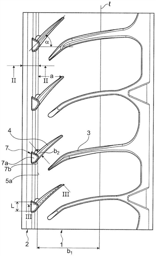
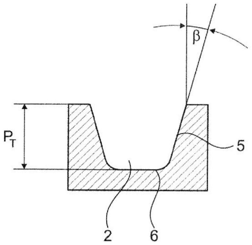
[0037] figure 1 Shown is a plan view (expanded in a plane) of the shoulder-side region of the tread having a shoulder-side rib 1 and circumferential grooves 2 delimiting said rib on the inner side of the tread, as figure 2 As shown in the cross-sectional illustration in , the circumferential groove has a depth P T , which corresponds to the tread depth provided for the corresponding tire. figure 1 The dashed line l in represents a lateral edge of the tire's ground-contacting surface. In the shown embodiment, the circumferential grooves 2 extend straight in the circumferential direction, but, like conventional circumferential grooves, they may also have a zigzag or wave shape. The patterned tread regions adjoining the circumferential grooves 2 on the tread inner side are not shown, and these patterned tread regions may fur...


PUM

PropertyMeasurementUnit
Maximum widthaaaaaaaaaa

Abstract

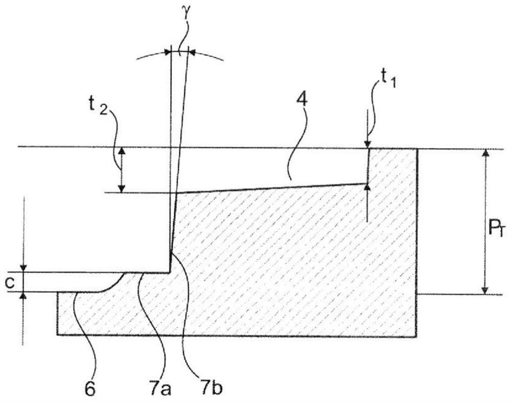
The invention relates to a pneumatic vehicle tire comprising a tread with circumferential grooves (2) and at least one profiled rib (1) which is continuous in the circumferential direction and in which grooves (4) are formed that open into a circumferential groove (2) delimiting the profiled rib (1) at a groove flank (5) of the circumferential groove, wherein the groove flanks (5) of the circumferential groove (2) run in the direction of the tread periphery at an angle (beta) of 12-degree to 17-degree relative to the radial direction, thereby expanding the circumferential groove (2). The grooves (4) run at an angle (alpha) of 45-degree + / - 20-degree relative to the axial direction, terminate within the profiled rib (1), have a maximum depth (t2) of 3.5 mm, and open into a respective localindentation (7) which is formed on the groove flank (5), reaches the tread periphery, is concavely rounded along the groove flank (5), and has a base (7a) running parallel to the tread periphery in particular, said base being located at a distance (c) of 0.5 mm to 2.0 millimeters in the radial direction from the lowest point of the groove base (6) of the circumferential groove (2).

Description

technical field [0001] The present invention relates to a pneumatic tire for vehicles having a tread including circumferential grooves and at least one rib extending in the circumferential direction and having Grooves are formed in the grooves which open into the circumferential groove at one of the groove sides laterally delimiting the ribs of the circumferential groove, wherein the groove sides of the circumferential groove are opposite to the radial The circumferential grooves extend at an angle of 12° to 17° such that the circumferential grooves widen in the peripheral direction of the tread. Background technique [0002] A pneumatic tire for vehicles with a tread of this type is known from EP 2 239 153 A1. The tread has a plurality of ribs separated from each other by circumferential grooves. On the shoulder side, transverse grooves traverse the provided ribs, which open by means of short portions of reduced depth into circumferential grooves delimiting the ribs on th...

Claims


Application Information

Patent Timeline
IPC IPC(8): B60C11/03B60C11/13
CPCB60C11/0309B60C11/1323B60C11/1353B60C2011/0341B60C2011/0362B60C2011/0365B60C2011/0369B60C2011/0381B60C2011/039B60C2011/1361B60C2011/0353B60C2011/0355B60C2011/133
Inventor 艾哈迈德·乌兹杜鲁拉尔夫·舒特伯恩哈德·勒格尔
Owner CONTINENTAL REIFEN DEUTSCHLAND GMBH
Learn More