Hybrid movable coil plate and flat-panel loudspeaker using the same

A moving coil and speaker technology, applied in the direction of sensors, circuit lead arrangement/elimination, magnetic objects, etc., can solve the problems of increased impedance, decreased mass production efficiency, large consumption, etc., to increase the induced electromotive force, realize impedance control, The effect of improving sound pressure

Active Publication Date: 2022-08-02
金东万 +1
View PDF7 Cites 0 Cited by
  • Summary
  • Abstract
  • Description
  • Claims
  • Application Information

AI Technical Summary

Problems solved by technology

[0007] The coiled copper wire movable coil starts from the outer contour of the coil track and ends on the inside of the coil track, so it is very difficult to electrically connect the + and - leads. In the case of winding with a single copper wire, in order to increase the "L" value However, it is necessary to increase the number of turns (Turn number) of the track. In this case, there is a problem that the impedance increases proportionally with the increase of the number of turns. In order to increase the number of turns while maintaining the impedance, thick copper wire winding is required. At this time There is a contradiction in the inversely proportional correlation relationship between the increase in the number of turns and the increase in the overall thickness and weight of the movable coil
[0008] In addition, in the case of a pattern-printed PCB movable coil, the two layers of the coil track type with a two-layer structure can only be connected in series. In the case of only series connection, the impedance increases proportionally with the number of turns of the coil track. large and thus not very efficient in controlling the impedance
[0009] Moreover, in the case of printing planar coil tracks on PCBs with a multi-layer structure of more than four layers, the number of turns can be increased through PCB fine process technology to increase the "L" value, and the efficiency can be improved through series and parallel combinations between layers. However, for the fine process of PCB and the PCB characteristics of multilayer structure, the formation of extremely wide dispersion in impedance management leads to a decrease in mass production efficiency. Therefore, the cost (Cost) of movable coils using multilayer PCBs increases, which cannot be significantly improved. The cost of components, the process of precision designing the PCB pattern of the multi-layer structure, printing the coil track, correcting the data of the product, and improving the design after each time is complicated and consumes a lot of money

Method used


Image

  • Hybrid movable coil plate and flat-panel loudspeaker using the same
  • Hybrid movable coil plate and flat-panel loudspeaker using the same
  • Hybrid movable coil plate and flat-panel loudspeaker using the same

Examples


no. 1 example

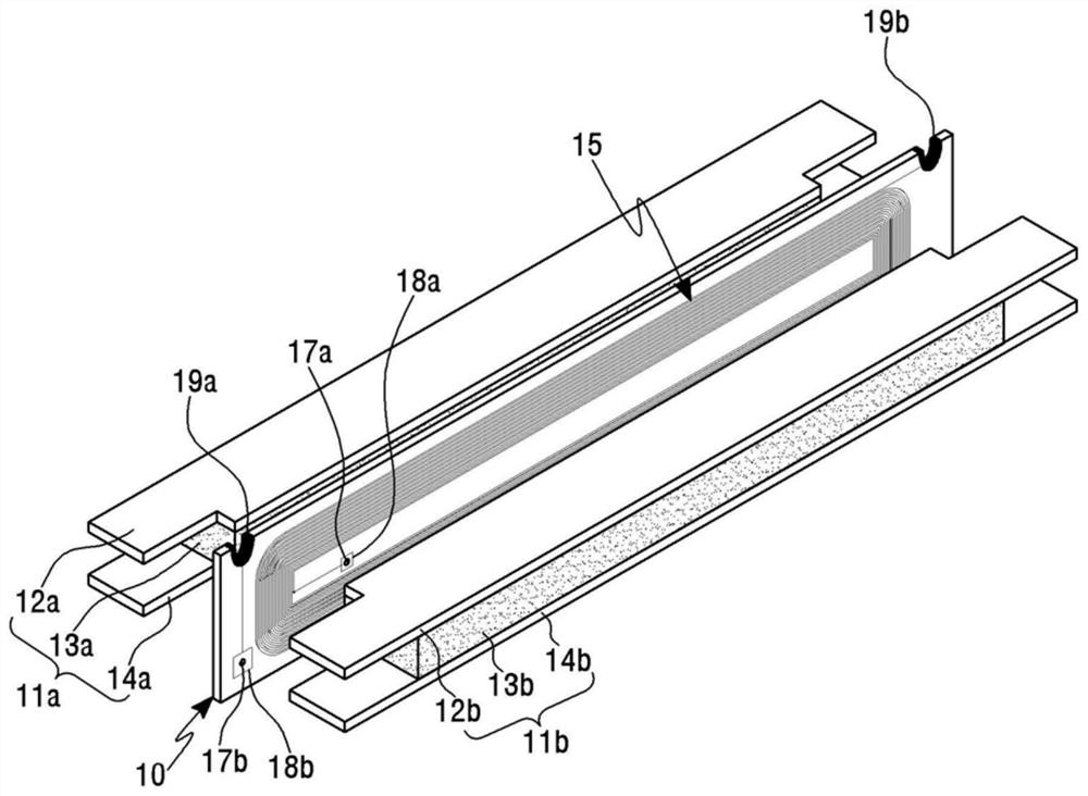
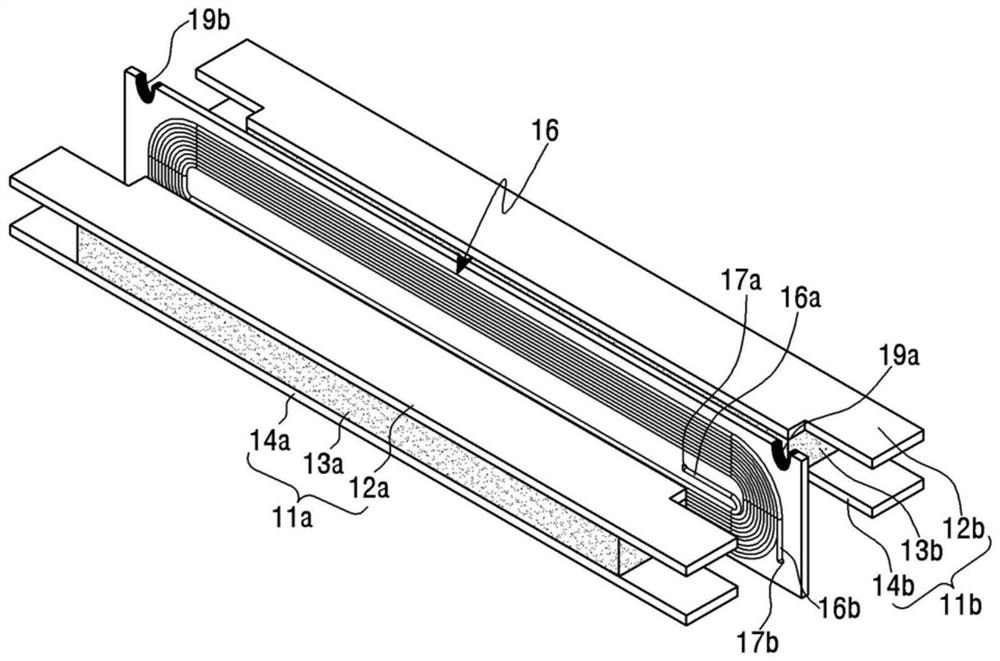
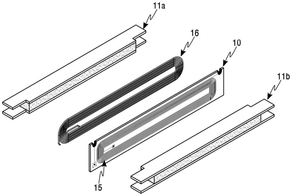
[0055] figure 1 It is a schematic perspective view of a flat-panel speaker including the hybrid movable coil plate according to the first embodiment of the present invention, figure 2 It is a schematic perspective view showing another angle of the flat-panel speaker including the hybrid movable coil plate according to the first embodiment of the present invention, image 3 It is an exploded perspective view of the copper wire coil of the flat-panel speaker including the hybrid movable coil plate of the first embodiment of the present invention, Figure 4 It is a sectional view of a flat-panel loudspeaker including the hybrid movable coil plate of the first embodiment of the present invention.

[0056] exist image 3 In order to facilitate the description and help understanding the arrangement relationship, only the copper wire coil 16 is disassembled and arranged on the side surface of the movable coil plate 10 , and the copper wire coil 16 is pasted on the side surface of ...

no. 2 example

[0075] Figure 5 It is a schematic perspective view of a flat-panel loudspeaker including a hybrid movable coil plate according to a second embodiment of the present invention, Image 6 It is an exploded perspective view of the copper wire coil of the flat-panel speaker including the hybrid movable coil plate of the second embodiment of the present invention, Figure 7 It is a cross-sectional view of a flat-panel loudspeaker including a hybrid movable coil plate according to a second embodiment of the present invention.

[0076] exist Image 6 In order to facilitate the description and help understanding the arrangement relationship, only the copper wire coil 26 is disassembled and arranged on the side surface of the first movable coil plate 20a, and the copper wire coil 26 is pasted on the side surface of the first movable coil plate 20a for use.

[0077] Comparing the second embodiment of the present invention with the first embodiment, it can be seen that the number of th...


PUM


Abstract

The present invention relates to a hybrid movable coil plate and a flat-panel loudspeaker, and more particularly to increasing the induced electromotive force by pattern-printing a coil on one side of the movable coil plate and a copper wire coil attached and wound on the other side. Hybrid movable coil plate and flat-panel loudspeaker that improves the sound pressure of the loudspeaker. The hybrid movable coil plate for a flat-panel speaker of the present invention is characterized in that a coiled copper wire coil is pasted on one side and a PCB coil is pattern-printed on the other side, the copper wire coil and the PCB coil are formed in the form of rails, and a pair of lead wires are formed to connect At the end, one or more through holes for electrical connection between the copper wire coil and the PCB coil and a copper plate located around at least one of the one or more through holes are formed.

Description

technical field [0001] The present invention relates to a hybrid movable coil plate and a flat-panel loudspeaker, and more particularly, to increasing the induced electromotive force by pattern-printing a coil on one side of the movable coil plate and a copper wire coil attached and wound on the other side, thereby increasing the induced electromotive force. Hybrid movable coil plates and flat-panel speakers that improve the sound pressure of speakers. Background technique [0002] The movable coil plate used in the flat-panel loudspeaker is formed by winding one or both sides of a plate-shaped coil base into an elliptical shape or by printing a pattern. [0003] When there is current flowing in the movable coil of the movable coil plate, the current flowing at this time generates a magnetic field that expands and contracts at the same frequency as the audio signal around the movable coil. Therefore, the movable coil plate moves up and down while interacting with the magnet...

Claims


Application Information

Patent Timeline
Patent Type & Authority Patents(China)
IPC IPC(8): H04R9/04H04R9/02H04R1/06
CPCH04R9/06H04R2209/041H04R9/047H04R9/025H04R1/06H01F7/02H01F7/081H04R9/046H05K1/115H05K1/165
Inventor 金东万
Owner 金东万
Why Eureka
Try Eureka