Closestool type female urine collector for medical clinical laboratory
A laboratory and collector technology, applied in the field of collectors, can solve the problems of urine being sprayed on hands, inconvenient for female patients to collect, and sprayed on hands, etc., to achieve the effect of convenient collection
- Summary
- Abstract
- Description
- Claims
- Application Information
AI Technical Summary
Problems solved by technology
Method used
Image
Examples
Embodiment 1
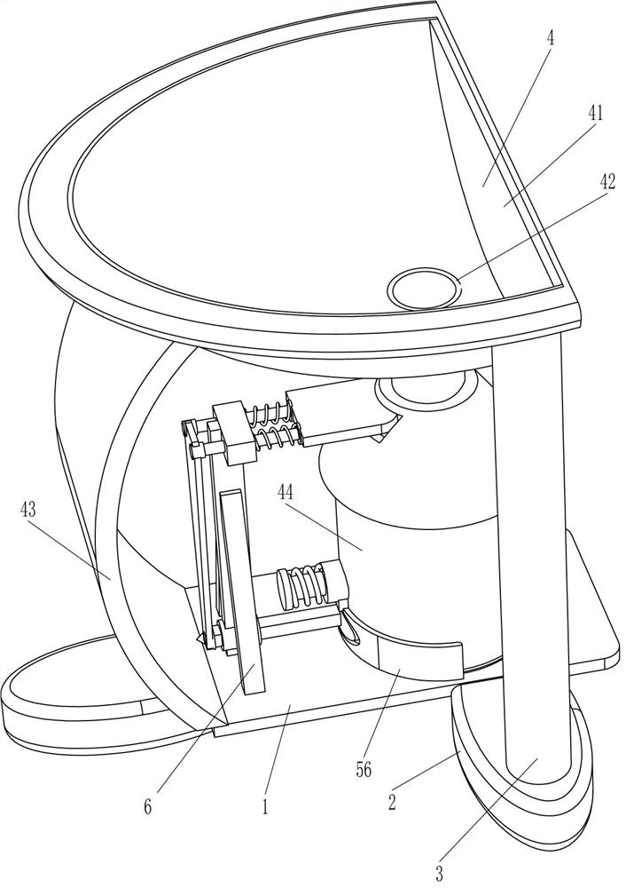
[0023] A kind of toilet type female urine collector for medical laboratory, such as figure 1 with image 3 As shown, it includes a bottom plate 1, a leg 2, a pillar 3, a collection mechanism 4 and a locking mechanism 5. The right side of the front and back sides of the bottom plate 1 and the middle part of the left side are fixedly connected with the legs 2, and the top and outer sides of the two legs 2 on the right are fixed. A pillar 3 is fixedly connected, and a collection mechanism 4 is provided between the top of the pillar 3 on the front and rear sides and the top left side of the bottom plate 1, and a locking mechanism 5 is provided on the bottom plate 1.
[0024] The collection mechanism 4 includes a toilet bowl 41, a liquid outlet pipe 42, an arc-shaped support plate 43, and a collection container 44. The toilet bowl 41 is fixedly connected between the tops of the front and rear pillars 3, and the bottom end of the toilet bowl 41 is connected with a liquid outlet pipe...
Embodiment 2
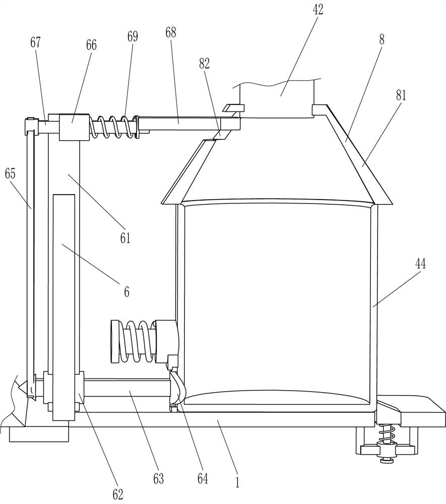
[0030] On the basis of Example 1, such as figure 1 with figure 2Shown, also comprise leak-proof mechanism 6, leak-proof mechanism 6 includes support plate 61, square hole cover 62, square bar 63, baffle plate 64, connecting rod 65, sliding sleeve 66, slide bar 67, sealing plate 68 and The second spring 69 is fixedly connected with a support plate 61 in the middle part on the left side of the top of the bottom plate 1, and the middle part of the bottom of the support plate 61 is fixedly pierced with a square hole sleeve 62, and the square hole sleeve 62 is slidingly provided with a square rod 63, and the right end of the square rod 63 A baffle 64 is fixedly connected, the right end of the baffle 64 runs through the arc-shaped plate 56 to cooperate with it, the left end of the square rod 63 is fixedly connected with a connecting rod 65, and the top of the support plate 61 is fixedly connected with a sliding sleeve 66, and the front and rear parts of the sliding sleeve 66 are sl...
Embodiment 3
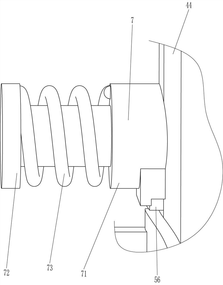
[0033] On the basis of embodiment 1 and embodiment 2, such as figure 2 and Figure 4 As shown, a push-out mechanism 7 is also included. The push-out mechanism 7 includes a conduit 71, a push rod 72 and a third spring 73. A conduit 71 is affixed to the middle of the top of the arc-shaped plate 56, and a push rod 72 is slidably arranged in the conduit 71. A third spring 73 is wound between the left end of the push rod 72 and the left side of the conduit 71 .
[0034] Also includes a splash-proof mechanism 8, the splash-proof mechanism 8 includes a conical cover 81, the bottom end of the liquid outlet pipe 42 is fixedly connected with a conical cover 81, the upper left side of the conical cover 81 has a through hole 82, and the sealing plate 68 penetrates Through the via hole 82 .
[0035] Initially, the third spring 73 is in a stretched state, and when the inclined-plane block 55 moves downward and disengages from the collection container 44, due to the action of the third sp...
PUM
 Abstract
Description
Claims
Application Information
 - R&D
- Intellectual Property
- Life Sciences
- Materials
- Tech Scout
- Unparalleled Data Quality
- Higher Quality Content
- 60% Fewer Hallucinations
Browse by: Latest US Patents, China's latest patents, Technical Efficacy Thesaurus, Application Domain, Technology Topic, Popular Technical Reports.
© 2025 PatSnap. All rights reserved.Legal|Privacy policy|Modern Slavery Act Transparency Statement|Sitemap|About US| Contact US: help@patsnap.com


