Clamp for numerical control machining

A kind of machining and fixture technology, which is applied in the direction of manufacturing tools, metal processing equipment, metal processing machinery parts, etc., can solve the problems that the workpiece cannot be processed, it is not worth it, and the chuck cannot effectively clamp various workpieces, etc., to achieve Strong adaptability and guaranteed stability

Inactive Publication Date: 2020-11-03
LIAONING INST OF SCI & TECH
View PDF7 Cites 3 Cited by
  • Summary
  • Abstract
  • Description
  • Claims
  • Application Information

AI Technical Summary

Problems solved by technology

[0004] When the existing fixtures clamp different workpieces, due to the different shapes of the workpieces, the collets used in the fixture cannot effectively clamp various workpieces. At this time, it is necessary to formulate a specific Fixtures are used to clamp the workpiece. If the number of such workpieces is small, especially when the shape of the workpiece is irregular and its surface is uneven, it is extremely unworthy to produce a specific fixture for such a small number of workpieces, but The workpiece cannot be processed without making a fixture. Therefore, it is necessary to provide a fixture that can adapt to the processing of various workpieces with complex shapes and uneven outer surfaces without affecting the stability of the workpiece clamped by the fixture.

Method used


Image

  • Clamp for numerical control machining
  • Clamp for numerical control machining

Examples


Embodiment Construction

[0032] Attached below figure 1 to attach figure 2 , a specific embodiment of the present invention will be described in detail, but it should be understood that the protection scope of the present invention is not limited by the specific embodiment.

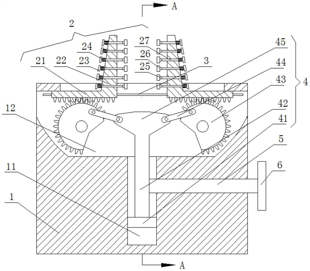
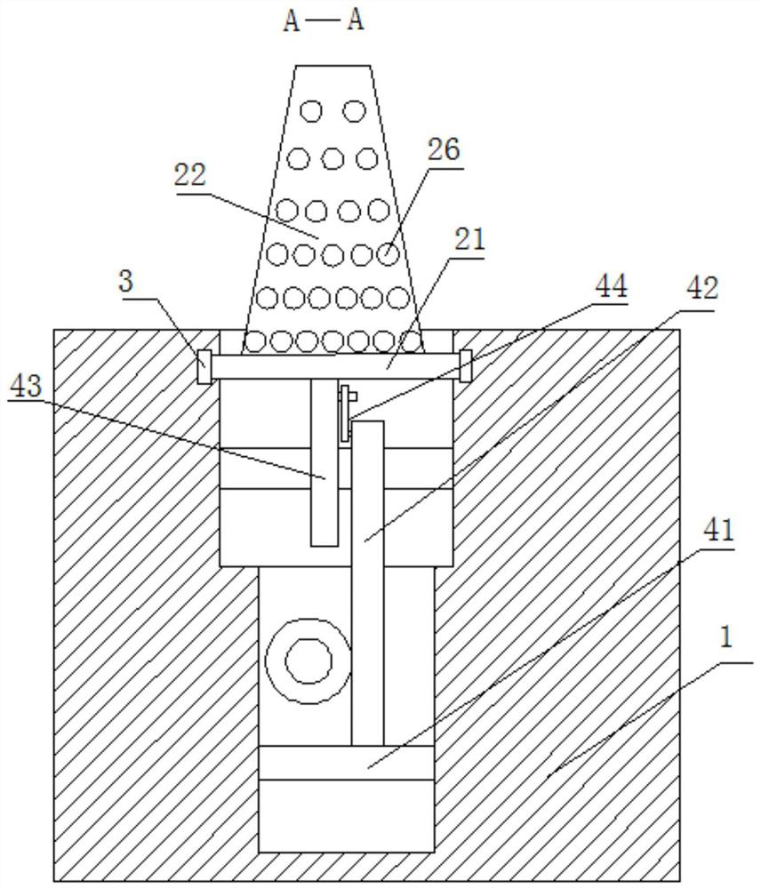
[0033] Embodiments of the present invention provide a fixture for numerical control machining, such as Figure 1 to Figure 2 As shown, it includes: a workbench 1, a slot 12 is opened on the top of the workbench 1, and two opposite clamping parts 2 are arranged in the slot 12.

[0034] The clamping part 2 includes: a connecting plate 21 arranged horizontally. The connecting plate 21 is slidably arranged in the slot 12 through the guide structure 3 . A plurality of contact portions 26 are evenly distributed on the side, and support plates 22 are pierced with support rods 27 arranged horizontally. One end of the support rods 27 is hinged with the contact portions 26, and the other end of the support rods 27 is provided with a lim...


PUM


Abstract

The invention relates to a clamp for numerical control machining. The clamp comprises a workbench and clamping parts; a slot is formed in the top of the workbench, and the two oppositely arranged clamping parts are arranged in the slot; each clamping part comprises a horizontally-arranged connecting plate, each connecting plate is arranged in the slot in a sliding manner through a guide structure,a supporting plate is fixed to the top of one end of each connecting plate, a plurality of contact parts are evenly distributed on the opposite sides of the two supporting plates, horizontally-arranged supporting rods are arranged on the supporting plates in a penetrating manner, one end of each supporting rod is hinged to the corresponding contact part, limiting tables are arranged at the otherends of the supporting rods, and springs are connected between the limiting tables and the surfaces, deviating from the contact parts, of the supporting plates; and the clamp further comprises a driving structure, and the driving structure is arranged on the workbench and used for driving the two clamping parts to move in the same direction or in the opposite directions. The clamp can be used forclamping various workpieces with complex appearances and different shapes, can ensure the clamping stability of the workpieces, and is worth of popularizing.

Description

technical field [0001] The invention relates to the technical field of machining, in particular to a fixture for numerical control machining. Background technique [0002] Fixture, a device used to fix the processing object in the process of mechanical manufacturing so that it occupies the correct position to accept construction or inspection. [0003] According to the characteristics of use, the types of fixtures can be divided into: universal fixtures, special fixtures, adjustable fixtures and combined fixtures. [0004] When the existing fixtures clamp different workpieces, due to the different shapes of the workpieces, the collets used in the fixture cannot effectively clamp various workpieces. At this time, it is necessary to formulate a specific Fixtures are used to clamp the workpiece. If the number of such workpieces is small, especially when the shape of the workpiece is irregular and its surface is uneven, it is extremely unworthy to produce a specific fixture for...

Claims


Application Information

Patent Timeline
IPC IPC(8): B23Q3/06
CPCB23Q3/061
Inventor 郎庆阳黄志东
Owner LIAONING INST OF SCI & TECH
Why Eureka
Try Eureka