Eureka AIR delivers breakthrough ideas for toughest innovation challenges, trusted by R&D personnel around the world.

Valve well capable of automatically removing water and conveniently opening and closing novel valve

A valve well and automatic technology, applied in the direction of valve operation/release device, valve details, valve device, etc., can solve the problems of new valve soaking, untimely drainage, corrosion, etc., and achieve the goal of reducing work intensity and increasing work space Effect

Inactive Publication Date: 2020-11-03
福州经济技术开发区易通元智能科技有限公司
View PDF0 Cites 1 Cited by
  • Summary
  • Abstract
  • Description
  • Claims
  • Application Information

AI Technical Summary

Problems solved by technology

[0002] The valve well is a well set up by the valve of the pipeline for the convenience of opening and closing part of the pipeline network operation or maintenance work. At present, the drainage of the valve well usually requires manual drainage. The work intensity of the workers is high, and the drainage is not timely, resulting in The new valve is soaked and corroded. The current manual opening of the new valve occasionally encounters the problem of turning the switch due to rust and other reasons. Usually, other tools are needed, and the space of the valve well is limited, so it is not very convenient to carry and operate.

Method used


Image

  • Valve well capable of automatically removing water and conveniently opening and closing novel valve
  • Valve well capable of automatically removing water and conveniently opening and closing novel valve
  • Valve well capable of automatically removing water and conveniently opening and closing novel valve

Examples


Embodiment Construction

[0019] All features disclosed in this specification, or steps in all methods or processes disclosed, can be combined in any way, except for mutually exclusive features and or steps.

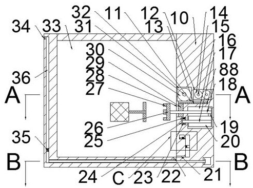
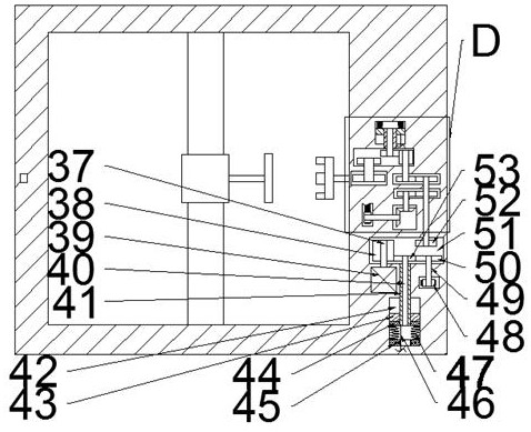
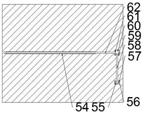
[0020] Combine below Figure 1-5 The present invention is described in detail, and for convenience of description, the orientations mentioned below are now stipulated as follows: figure 1 The up, down, left, right, front and back directions of the projection relationship itself are the same.

[0021] Such as Figure 1-5As shown, a valve well that automatically removes water and is convenient to open and close a new type of valve of the device of the present invention includes a main box body 10, and a valve well cavity 33 with an upward opening is provided in the main box body 10, and the valve well cavity The right side of the 33 is communicated with a telescopic chamber 28, and the right side of the telescopic chamber 28 is connected with a rack chamber 88 extending to the right. The lower en...


PUM


Abstract

The invention discloses a valve well capable of automatically removing water and conveniently opening and closing a novel valve. The valve well comprises a box body, wherein a valve well cavity with an upward opening is formed in a main box body, a telescopic cavity is formed in the right side of the valve well cavity in a communicating mode, a rack cavity extending rightwards is formed in the right side of the telescopic cavity in a communicating mode, a rack plate is connected to the lower end wall of the rack cavity in a sliding fit mode, a rack is fixedly connected to the upper end surfaceof the rack plate, and a wide tooth cavity located in the lower side of the rack cavity is formed in the right side of the telescopic cavity; a screw rotates to drain accumulated water in the valve well cavity through a water leakage cavity, a screw cavity and a drainage cavity, the accumulated water detection and drainage are achieved, the working intensity for manual detection is reduced, a novel valve in the valve well is prevented from being soaked and corroded, a rotary disc and a rotary disc block rotate, and a switch ring is rotated to open the novel valve. The operators are help to open the novel valve difficult to rotate, and the rotary disc and the rotary disc block are moved to be close to the right end wall of the valve well cavity, so that the working space used by the operators is enlarged.

Description

technical field [0001] The invention relates to the related technical field of new valves, in particular to a valve well which automatically removes water and facilitates the opening and closing of new valves. Background technique [0002] The valve well is a well set up by the valve of the pipeline for the convenience of opening and closing part of the pipeline network operation or maintenance work. At present, the drainage of the valve well usually requires manual drainage. The work intensity of the workers is high, and the drainage is not timely, resulting in The new valve is soaked and corroded. The current manual opening of the new valve occasionally encounters the problem of turning the switch due to rust and other reasons. Usually, other tools are needed, and the space of the valve well is limited, so it is not very convenient to carry and operate. . Contents of the invention [0003] Aiming at the deficiencies of the above-mentioned technologies, the present inven...

Claims


Application Information

Patent Timeline
IPC IPC(8): E02D29/12F16K31/04F16K31/53F16K31/54
CPCE02D29/12E02D29/125F16K31/043F16K31/535F16K31/54
Inventor 刘端奎
Owner 福州经济技术开发区易通元智能科技有限公司
Why Eureka
Eureka Blog
Learn More