Rolling brush convenient to carry and replace
A rolling brush and roller technology, applied in the field of rolling brushes that are easy to carry and replace, can solve the problems of increasing the use cost of rolling brushes, shedding of bristles, and short service life, so as to save replacement time, increase connection tightness, and be easy to carry with the effect of fetching
- Summary
- Abstract
- Description
- Claims
- Application Information
AI Technical Summary
Problems solved by technology
Method used
Image

Examples
Embodiment 1
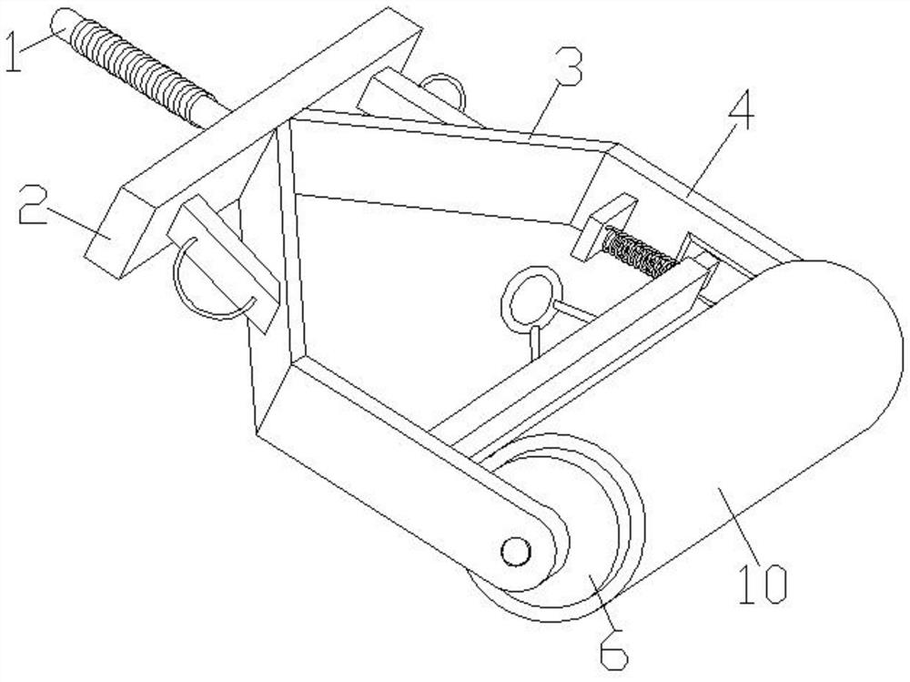
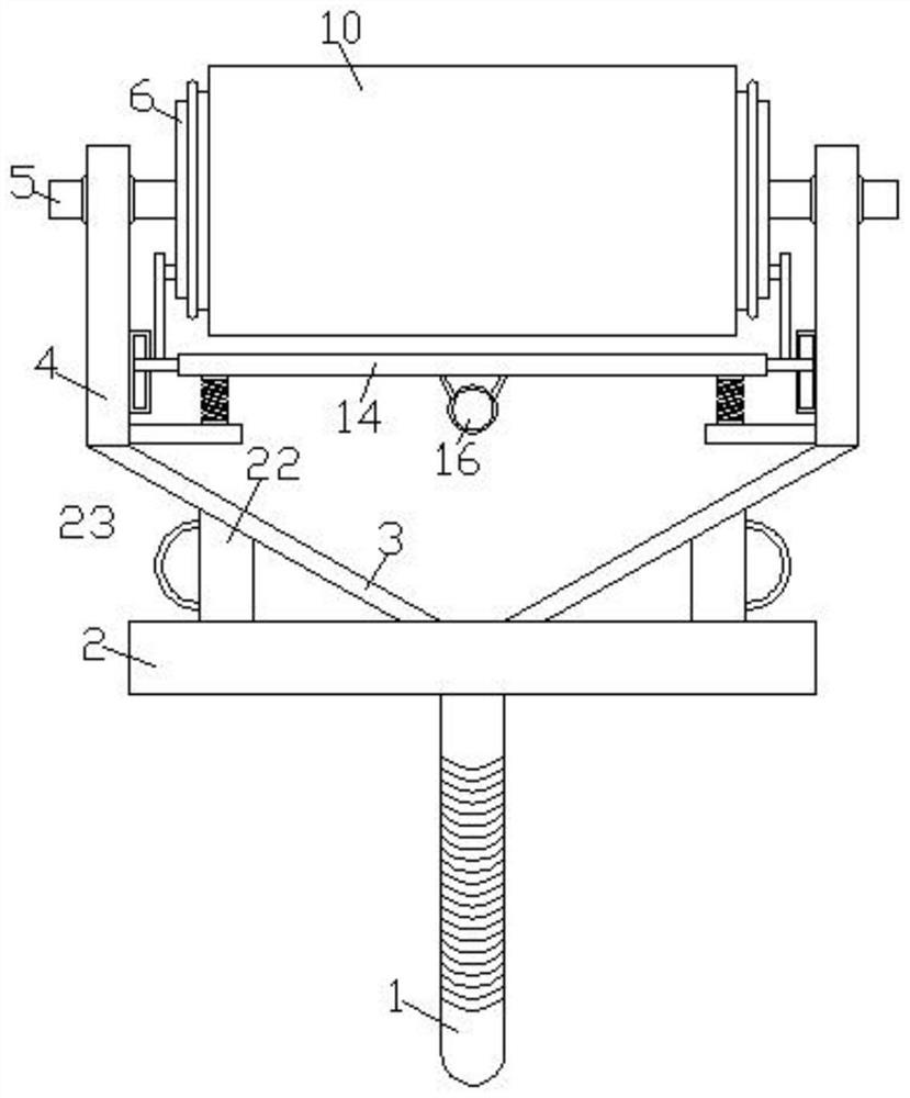
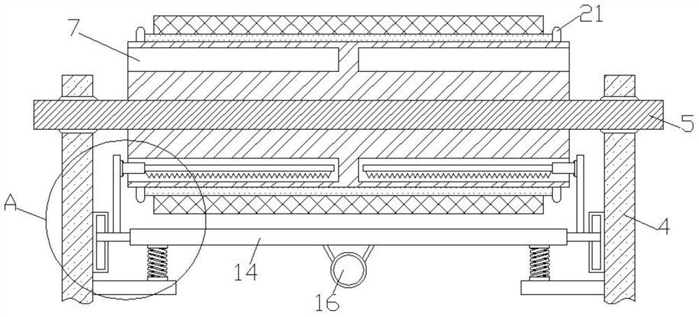
[0039] Such as Figure 1-5 As shown, a rolling brush that is easy to carry and replace includes a handle 1, a connecting plate 2 is fixedly installed at one end of the handle 1, and an anti-slip coil is wound on the outer surface of the handle 1, and the anti-slip coil can increase the distance between the user's palm and The friction between the handles 1 avoids the phenomenon of hands-off. The side of the connecting plate 2 away from the handle 1 is fixedly installed with two symmetrical sloping plates 3, and the side of the connecting plate 3 away from the connecting plate 2 is fixedly installed. There is a straight plate 4, the slant plate 3 and the straight plate 4 are connectors for the connection between the connecting plate 2 and the drum 6, a connecting rod 5 is movably connected between the two straight plates 4, and the outer surface of the connecting rod 5 is fixedly installed with Cylinder 6, two symmetrical annular grooves 7 are provided inside the cylinder 6. Wh...
Embodiment 2
[0047] Such as Figure 6 As shown, the difference between this embodiment and Embodiment 1 is that the top surface of the tool mounting seat 19 in this embodiment is an arc-shaped curved surface, and the arc-shaped curved surface of the tool mounting seat 19 is concave inward, and the tool mounting seat 19 is The curved curved surface of 19 is closely attached to the inner wall of the annular groove 7 .
[0048] The top surface of the tool mounting seat 19 is set as an arc-shaped curved surface, so that the tool mounting seat 19 and the inner wall of the annular groove 7 are more fit, and the contact area between the top surface of the tool mounting seat 19 and the inner wall of the annular groove 7 is increased, so that the two contact More stable during, thereby alleviate when cylinder 6 rotates, the vibration that tool mount 19, cross plate 14 produces, improves the brushing effect of roller brush.
Embodiment 3
[0050] Such as Figure 7 As shown, the difference between this embodiment and Embodiment 1 and Embodiment 2 is that all sides of the tool mounting seat 19 are rectangular, and the top surface of the tool mounting seat 19 is provided with two groups of connecting wheel mechanisms 24, two groups of The connecting wheel mechanism 24 is evenly arranged on the side of the tool mounting seat 19. The connecting wheel mechanism 24 includes a bottom plate, which is fixedly connected with the tool mounting seat 19. Two symmetrical There is a vertical plate, a rotating rod is movably connected between the two vertical plates, and the outer surface of the rotating rod is fixedly equipped with rollers, and the surface of the rollers away from the bottom plate contacts with the inner wall of the annular groove 7.
[0051] Through the two sets of multiple connecting wheel mechanisms 24 provided, the tool mounting seat 19 can be stably contacted with the inner wall of the annular groove 7, an...
PUM
 Abstract
Description
Claims
Application Information
 - R&D
- Intellectual Property
- Life Sciences
- Materials
- Tech Scout
- Unparalleled Data Quality
- Higher Quality Content
- 60% Fewer Hallucinations
Browse by: Latest US Patents, China's latest patents, Technical Efficacy Thesaurus, Application Domain, Technology Topic, Popular Technical Reports.
© 2025 PatSnap. All rights reserved.Legal|Privacy policy|Modern Slavery Act Transparency Statement|Sitemap|About US| Contact US: help@patsnap.com