Self-adaptive damper and device based on damper

A damper and self-adaptive technology, used in shock absorbers, shock absorbers, springs/shock absorbers, etc., can solve problems such as poor impact resistance, single buffer structure, and inability to adapt, and achieve reasonable structure and application range. Extensive and practical effects

Pending Publication Date: 2020-11-03
SHANGHAI JIAO TONG UNIV
View PDF1 Cites 4 Cited by
  • Summary
  • Abstract
  • Description
  • Claims
  • Application Information

AI Technical Summary

Problems solved by technology

The traditional friction damper is to give the friction surface a certain amount of preload by means of high-strength bolts and interference contact. When the shock or vibration comes, the friction surface overcomes the sliding friction and generates relative motion, so as to achieve the purpose of energy consumption. Due to the fixed pressure between the friction surfaces of the traditional friction damper, the friction adjustment of the friction damper can buffer or adjust the magnitude of shock and vibration constant, which cannot meet the current actual needs
[0004] Patent document CN209130098U discloses a novel spring damper and a socket cover structure containing the spring damper. The novel spring damper includes a damping frame and a spring. The damping frame includes a limiting plate and a In the middle of the side end surface and protruding outward, one end of the spring is sleeved on the outer periphery of the extension, and the outer diameter of the spring is smaller than the size of the limiting plate; the spring is in a non-compressed state The axial length is greater than the length of the extension; the center of the extension is provided with a through hole through the damping frame in the axial direction, but when this design is subjected to a strong impact, the buffer structure is single and the impact resistance is poor

Method used


Image

  • Self-adaptive damper and device based on damper
  • Self-adaptive damper and device based on damper
  • Self-adaptive damper and device based on damper

Examples


Embodiment Construction

[0069] The present invention will be described in detail below in conjunction with specific embodiments. The following examples will help those skilled in the art to further understand the present invention, but do not limit the present invention in any form. It should be noted that those skilled in the art can make several changes and improvements without departing from the concept of the present invention. These all belong to the protection scope of the present invention.

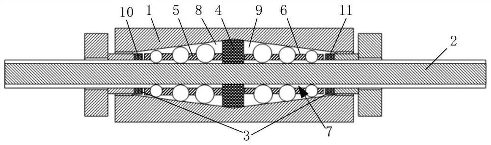
[0070] The present invention provides an adaptive damper, such as figure 1 As shown, it includes a device housing 1, a functional rod 2, a first elastic assembly 3, a second elastic assembly 4, a first damping adjustment assembly 5, and a second damping adjustment assembly 6, and the device housing 1 is provided with a movement channel 7. The functional rod 2 passes through the movement channel 7 and is separated from the device housing 1 by the second elastic component 4 installed in the device housing...


PUM


Abstract

The invention provides a self-adaptive damper and a device based on the damper. The self-adaptive damper comprises a device shell, a functional rod, a first elastic assembly, a second elastic assembly, a first damping adjusting assembly and a second damping adjusting assembly. The functional rod penetrates through a movement channel in the device shell, a first containing space and a second containing space are formed between the functional rod and the device shell, and the first damping adjusting assembly and the second damping adjusting assembly are installed in the first containing space and the second containing space respectively. The second elastic assembly is installed between the first damping adjusting assembly and the second damping adjusting assembly, the first elastic assemblycomprises a first elastic body and a second elastic body, and the first elastic body and the second elastic body are installed at the two ends of the device shell respectively. According to the damper, the damping-adjustable self-adaptive vibration attenuation and buffering can be achieved under the condition of vibration impact, various vibration and impact scenes can be solved, and the damper isflexible in structure and wide in application range.

Description

technical field [0001] The present invention relates to the technical field of dampers, in particular to an adaptive damper and a device based on the damper. Background technique [0002] The friction damper is one of the various dampers widely studied at home and abroad. Since the end of the 1970s, in order to meet the energy consumption and vibration reduction requirements of different building structures, engineering researchers have developed a variety of different types of dampers. The friction damper in this form is not only used in new passive control structures in many countries, but also in the anti-vibration reinforcement of structures and in improving the anti-vibration performance of wooden structures. [0003] Friction damper is a kind of friction force generated by the relative motion of the friction surface in a pressurized environment, so that the external input energy is converted into other forms of energy, so as to realize the change of the motion state of...

Claims


Application Information

Patent Timeline
Patent Type & Authority Applications(China)
IPC IPC(8): F16F13/00F16F9/53F16F9/32F16F9/34F16F9/50
CPCF16F9/3207F16F9/3405F16F9/50F16F9/535F16F13/007
Inventor 杨斌堂
Owner SHANGHAI JIAO TONG UNIV
Why Eureka
Try Eureka