LED lighting device and vehicle lamp

A technology of LED lighting and LED lights, which is applied in the field of lighting, can solve the problems of thick screen body, poor durability, and inability to realize single-pixel drive, etc., and achieve the effect of light and thin body, improved brightness and brightness uniformity

Active Publication Date: 2022-07-22
GUAN YEOLIGHT TECH CO LTD
View PDF5 Cites 0 Cited by
  • Summary
  • Abstract
  • Description
  • Claims
  • Application Information

AI Technical Summary

Problems solved by technology

[0003] However, many of the existing LED taillights cannot achieve single-pixel drive
Some tail lights using mini LED or micro LED solutions, due to optical design, have the problems of thick screen body, uneven light emitting area, cross light between light emitting areas, high temperature, poor durability and poor surface transparency.

Method used


Image

  • LED lighting device and vehicle lamp
  • LED lighting device and vehicle lamp
  • LED lighting device and vehicle lamp

Examples


Embodiment 1

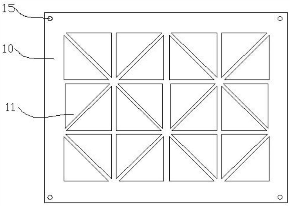
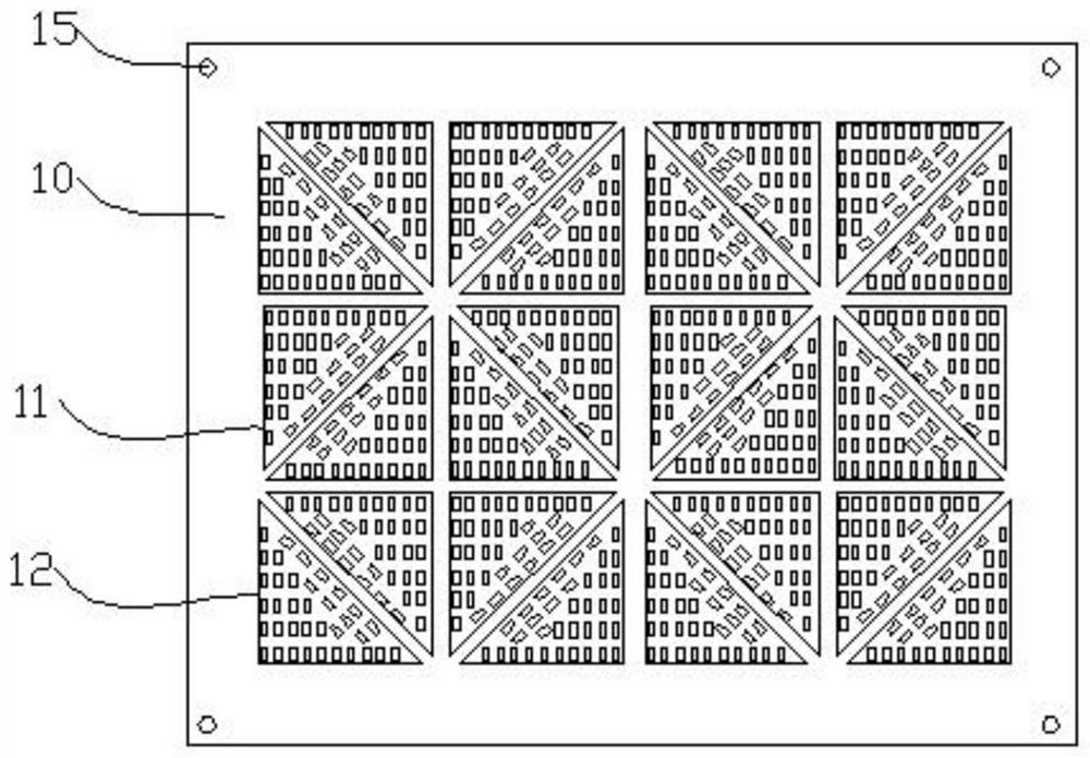
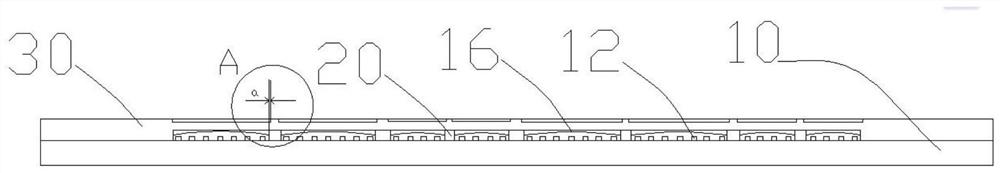
[0041] like Figure 1 to Figure 3 and Figure 4b As shown, this embodiment provides an LED lighting device, including a substrate 10, a sub-light-emitting area 11 disposed on the substrate 10; 36 LED lamps are arranged in the sub-light-emitting area 11; each of the sub-light-emitting areas 11 Independently controlled lead wires 13 and driving units 14 are provided; the driving unit 14 corresponding to each sub-light-emitting area 11 controls the on / off of the LED lights in the sub-light-emitting area through the lead wires 13 .

[0042] The distribution shape of the LED lamps 12 in the sub-light-emitting area 11 follows the arrangement shape of the sub-light-emitting area 11, that is, the outline shape of the distribution shape of the LED lamps 12 is consistent with the layout shape of the sub-light-emitting area 11, and The common center point is, for example, a right-angled triangle, except that the distribution contour shape of the LED lights 12 is nested in the sub-light-...

Embodiment 2

[0088] like Figure 35-39 As shown, this embodiment provides a vehicle lamp 40, the vehicle lamp is formed by splicing the LED lighting device in Embodiment 1, for example, made of figure 1 The first LED lighting device 51 shown and Figure 35 The second LED lighting device 52 shown is formed by fixed connection through the alignment of the mounting holes 15 Figure 36 lights shown.

[0089] Correspondingly, the independent control of different sub-light-emitting regions of different LED lighting devices can form a "display" pattern to realize the interaction of vehicle lights. such as Figure 37 When the lamp shown is used as a left rear lamp, when the sub-light-emitting area of ​​the shadow part in the lamp is illuminated, a prompt pattern of the vehicle to "turn left" can be realized, such as: Figure 38 When the car light shown is used as the right rear light, when the sub-light-emitting area of ​​the shadow part in the light is lit, the prompt pattern of the car to "...


PUM

PropertyMeasurementUnit
thicknessaaaaaaaaaa
areaaaaaaaaaaa
thicknessaaaaaaaaaa

Abstract

The present application discloses an LED lighting device and a vehicle lamp, comprising a substrate and a sub-light-emitting area disposed on the substrate; one or more LED lights are arranged in the sub-light-emitting area; each of the sub-light-emitting areas is provided with an independent Controlled leads and drive units; LED lights are evenly distributed in the sub-light-emitting regions, and the distribution shape follows the shape of the arrangement of the sub-light-emitting regions; the adjacent sub-light-emitting regions pass through the shading fixed on the substrate The sub-light-emitting area is also covered with a light-guiding plate; the light-guiding plate is engraved with at least one circle of light-guiding light that conforms to the shape of the sub-light-emitting area. The present application improves the brightness uniformity of the LED lighting device, which not only meets the brightness and reliability requirements of the LED lighting device used as a vehicle lamp, but also meets the brightness uniformity requirements of the "surface light source".

Description

technical field [0001] The present invention generally relates to the technical field of lighting, and in particular relates to an LED lighting device and a vehicle lamp. Background technique [0002] Due to the development of automobile intelligent interaction technology, the display of vehicle lights has become an important development trend in the future. For example, headlights can provide corresponding information to drivers and other relevant parties on the road through intelligent projection; and the future display design of tail lights , more in the display design of the taillights themselves. At the same time, with the development of vehicle lamp modeling requirements, people put forward the requirements of displayability, uniform lighting, beautiful appearance and comfort for automobile tail lamps. [0003] However, many of the existing LED tail lights cannot be driven by a single pixel. Some taillights using mini LED or microLED solutions have problems due to op...

Claims


Application Information

Patent Timeline
Patent Type & Authority Patents(China)
IPC IPC(8): F21S43/14F21S43/236F21S43/50F21V23/00F21V23/02F21W107/10F21Y115/10
CPCF21S43/14F21S43/236F21S43/50F21V23/002F21V23/003F21V23/02F21W2107/10F21Y2115/10B60Q1/549B60Q1/5035
Inventor 鲁天星张国辉李瀚斌吴海燕胡永岚
Owner GUAN YEOLIGHT TECH CO LTD
Why Eureka
Try Eureka