Dark field, bright field, phase contrast, fluorescence multi-mode synchronous imaging microscope imaging device

A technology of simultaneous imaging and microscopic imaging, applied in microscopes, optics, optical components, etc., can solve the problems of waste of time optical components, single imaging mode, different optical arrangements, etc., to achieve the effect of easy implementation, filling gaps, and simple operation

Active Publication Date: 2021-04-02
UNIV OF SHANGHAI FOR SCI & TECH
View PDF6 Cites 0 Cited by
  • Summary
  • Abstract
  • Description
  • Claims
  • Application Information

AI Technical Summary

Problems solved by technology

In the paper "Quantitative phase imaging using a partitioned detection aperture" (OPTICS LETTERS / Vol.37, No.19 / October 1, 2012), a non-interferometric technique is described for quantitative phase contrast imaging, but still only a single imaging mode
[0003] Although bright-field, dark-field and phase-contrast images provide complementary information on the specimen, simultaneous acquisition of these images in conventional microscopy is not feasible because each modality requires a different optical arrangement and specialized optical components
In addition, the conversion between imaging modes is accompanied by the waste of time and additional optical components, which is not energy-saving and convenient.
In the papers "Real-time brightfield, darkfield, and phase contrast imaging in a light-emitting diode array microscope" (Journal of Biomedical Optics 19(10), 106002(October2014)) and Microscopy refocusing and dark-field imaging by using a simple LEDarray (October 15,2011 / Vol.36,No.20 / OPTICS LETTERS), both proposed a method of using LED arrays to realize multi-mode illumination imaging, but none of them can solve the problem of synchronous imaging, and need to switch light sources frequently to obtain expected result
[0004] In addition, the existing fluorescence detection microscopes in the market have single functions and can only realize the fluorescence detection of specific substances

Method used


Image

  • Dark field, bright field, phase contrast, fluorescence multi-mode synchronous imaging microscope imaging device
  • Dark field, bright field, phase contrast, fluorescence multi-mode synchronous imaging microscope imaging device
  • Dark field, bright field, phase contrast, fluorescence multi-mode synchronous imaging microscope imaging device

Examples


Embodiment Construction

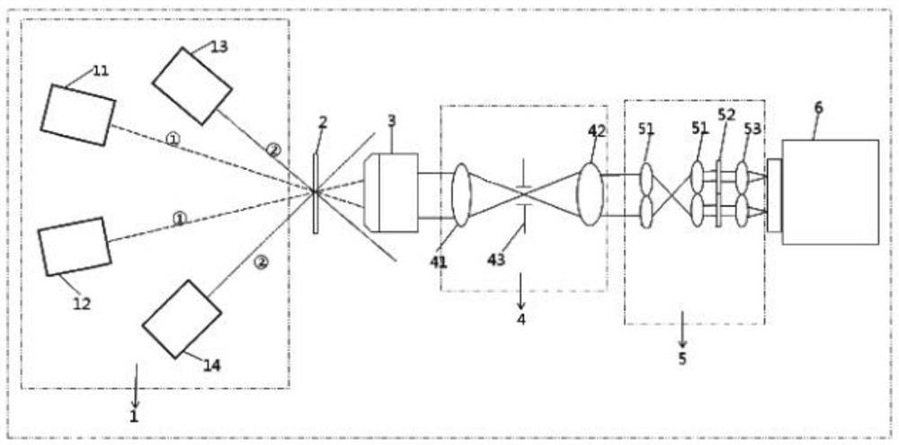
[0019] see Figure 1 to Figure 3 , a dark field, bright field, phase contrast, fluorescence multi-mode synchronous imaging microscope imaging device, with a sample stage 2, the focal point of the objective lens of the sample stage 2 is used to place samples, and one side of the sample stage is provided with several sets A beam emitting unit 1 formed by arranging light sources of different wavelengths, a beam processing unit 3 is arranged in sequence on the other side of the sample stage 2, a beam amplification unit 4 for amplifying the beam to ensure that the spot is completely irradiated on the beam filtering unit 5, and a beam Filter unit 5 and beam receiving unit 6 .

[0020] The sample stage 2 is a platform that can be moved up and down to ensure that the beam convergence point is irradiated on the sample.

[0021] In this embodiment, the beam emitting unit is used to emit light of different wavelengths at different angles, and has a 405nm laser 11, a 488nm laser 12, a 53...


PUM


Abstract

The invention discloses a dark field, bright field, phase contrast and fluorescent multi-mode synchronous imaging microscopic imaging device. The device is provided with a sample stage, wherein the focus of an objective lens on the sample stage is used for placing a sample, a light beam transmitting unit formed by a plurality of light sources which are arranged and have different wavelengths is arranged at one side of the sample stage, a light beam processing unit, a light beam amplifying unit, a light beam filtering unit and a light beam receiving unit are sequentially arranged at the other side of the sample stage, and the light beam amplifying unit is used for amplifying a light beam to guarantee that a light spot is completely irradiated to the light beam filtering unit. The device disclosed by the invention is applicable to biological observation and detection, is easy to use and low in cost and has good imaging effect.

Description

technical field [0001] The invention relates to an imaging device, in particular to a dark field, bright field, phase contrast and fluorescence multi-mode synchronous imaging microscopic imaging device. Background technique [0002] Light microscopy is a ubiquitous tool in different disciplines, providing detailed visualization of materials and biological specimens. Continuous advances in microscopy over the past few decades have introduced many new imaging modalities. However, brightfield, darkfield and phase contrast microscopy still represent the most common and widely used non-stain imaging methods. Brightfield (BF) microscopy provides images by mapping the intensity modulation of light passing through a sample. Although it is the simplest and most common form of microscopy, it is not suitable for viewing translucent samples, such as unlabeled cells and thin tissue samples, because these samples do not exhibit strong attenuation under visible light. Darkfield (DF) mic...

Claims


Application Information

Patent Timeline
Patent Type & Authority Patents(China)
IPC IPC(8): G02B21/18G02B21/14G02B21/12G02B21/10G02B21/36
CPCG02B21/10G02B21/125G02B21/14G02B21/18G02B21/361
Inventor 戴博周正萌张大伟王凯民郑璐璐
Owner UNIV OF SHANGHAI FOR SCI & TECH
Why Eureka
Try Eureka