
Miniature laser marking instrument mounting structure applied to cable bridge construction

A technology of laser marking instrument and cable tray, which is applied in the direction of cable installation, cable installation device, and cable installation tool, etc. It can solve the problems of difficulty in meeting the construction requirements of cable tray, long leveling time, and low leveling accuracy. Achieve high practical and promotional value, reasonable structure and simple operation

Pending Publication Date: 2020-11-03
CHINA THIRD METALLURGICAL GRP
View PDF0 Cites 0 Cited by
  • Summary
  • Abstract
  • Description
  • Claims
  • Application Information

AI Technical Summary

Problems solved by technology

During the use of the laser line marker, it is often necessary to level the laser line marker and the mounting base of the laser line marker before use, but most of the existing mounting bases rely on manual leveling. However, in In the process of manual leveling, there are often defects of low leveling accuracy and long leveling time, which makes it difficult to meet the construction requirements of cable bridges. Therefore, we have improved this and proposed a miniature laser marker used in cable bridge construction. Line instrument installation structure

Method used


Image

  • Miniature laser marking instrument mounting structure applied to cable bridge construction
  • Miniature laser marking instrument mounting structure applied to cable bridge construction
  • Miniature laser marking instrument mounting structure applied to cable bridge construction

Examples


Embodiment

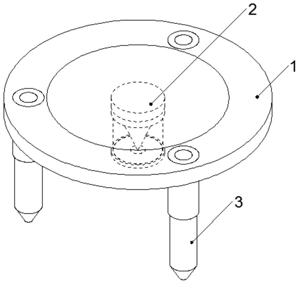
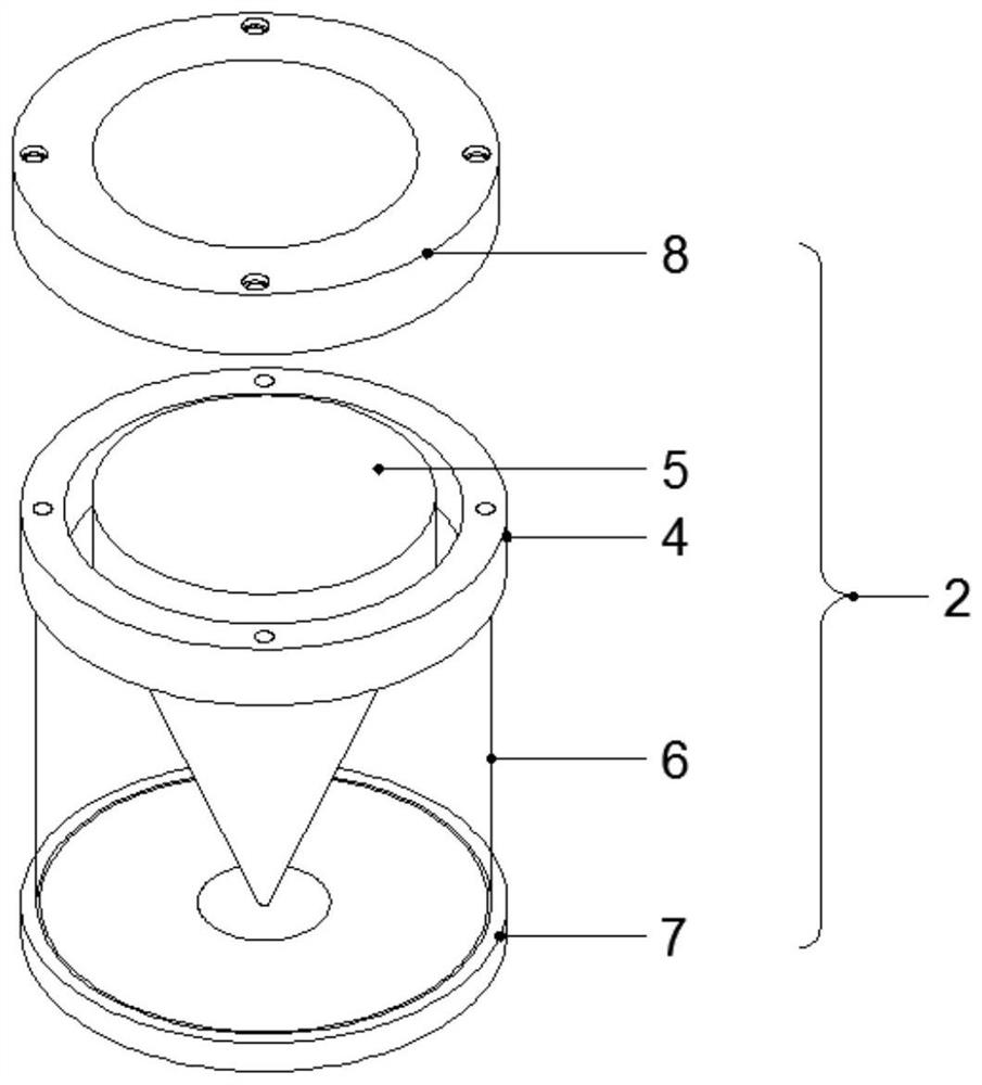
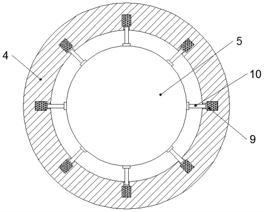
[0022] Example: such as Figure 1-5 As shown, the installation structure of a miniature laser marking instrument used in the construction of a cable bridge according to the present invention includes an installation base 1, the installation base 1 is circular, and a detection device 2 is fixedly installed at the center of the bottom circle. The device 2 is composed of a detection ring 4 and a detection cone 5, and the top section of the detection cone 5 is cylindrical, the detection ring 4 is fixedly sleeved on the outside of the detection cone 5 cylindrical section, and the inner ring of the detection ring 4 A number of installation holes are provided, and a pressure sensor 9 is fixedly installed in the installation holes, and the outer surface of the cylindrical section of the detection cone 5 is connected with a connecting rod 10 at a position corresponding to each installation hole, and the connecting rod 10 are respectively connected with the detection end of the pressure...


PUM


Abstract

The invention discloses a miniature laser marking instrument mounting structure applied to cable bridge construction, which comprises a mounting base, the mounting base is circular, a detection deviceis fixedly mounted at the circle center of the bottom, the detection device is composed of a detection ring and a detection cone, and one section of the top of the detection cone is cylindrical; thedetection ring is fixedly arranged on the outer side of the cylindrical section of the detection cone in a sleeving mode, a plurality of installation holes are formed in the inner ring of the detection ring, pressure sensors are fixedly installed in the installation holes, connecting rods are connected to the positions, corresponding to the installation holes, of the outer side face of the cylindrical section of the detection cone, and the connecting rods are connected with the detection ends of the pressure sensors respectively. Three sets of supporting devices are fixedly mounted on the edgeof the bottom face of the mounting base. The miniature laser marking instrument mounting structure applied to cable bridge construction is reasonable in structure and novel in design, can effectivelyreplace manpower to level and adjust the laser marking instrument, achieves automatic leveling of the laser marking instrument, and has relatively high practical and promotional values.

Description

technical field [0001] The invention relates to the technical field of cable bridge construction, in particular to an installation structure for a miniature laser marking instrument used in cable bridge construction. Background technique [0002] The laser marking instrument is also called the laser level. The laser level is a level that guides the laser beam emitted by the laser device into the telescope tube of the level to make it shoot out along the collimation axis. There are two types of laser level: a special laser level and a laser device attached to the level. It can be used for leveling measurement by cooperating with a leveling rod equipped with a photoelectric receiving target. Compared with the optical level, the laser level has the characteristics of high precision, long line of sight and automatic reading and recording. [0003] In the cable bridge construction of the cable tunnel, the laser marking instrument is one of the frequently used tools. During the ...

Claims


Application Information

Patent Timeline
Patent Type & Authority Applications(China)
IPC IPC(8): G01C15/00H02G1/00
CPCG01C15/004H02G1/00H02G2200/30
Inventor 赵晓姣刘剑丰任涛李波张焕哲
Owner CHINA THIRD METALLURGICAL GRP
Learn More