Calculation method for cutting track of ultrasonic elliptical vibration cutting technology
A technology of elliptical vibration and calculation method, which is applied in the calculation of cutting trajectory of ultrasonic elliptical vibration cutting technology, and in the field of calculation of cutting trajectory, which can solve the problems of increasing the surface shape error and overcut of the processed surface
- Summary
- Abstract
- Description
- Claims
- Application Information
AI Technical Summary
Problems solved by technology
Method used
Image
Examples
specific Embodiment approach 1
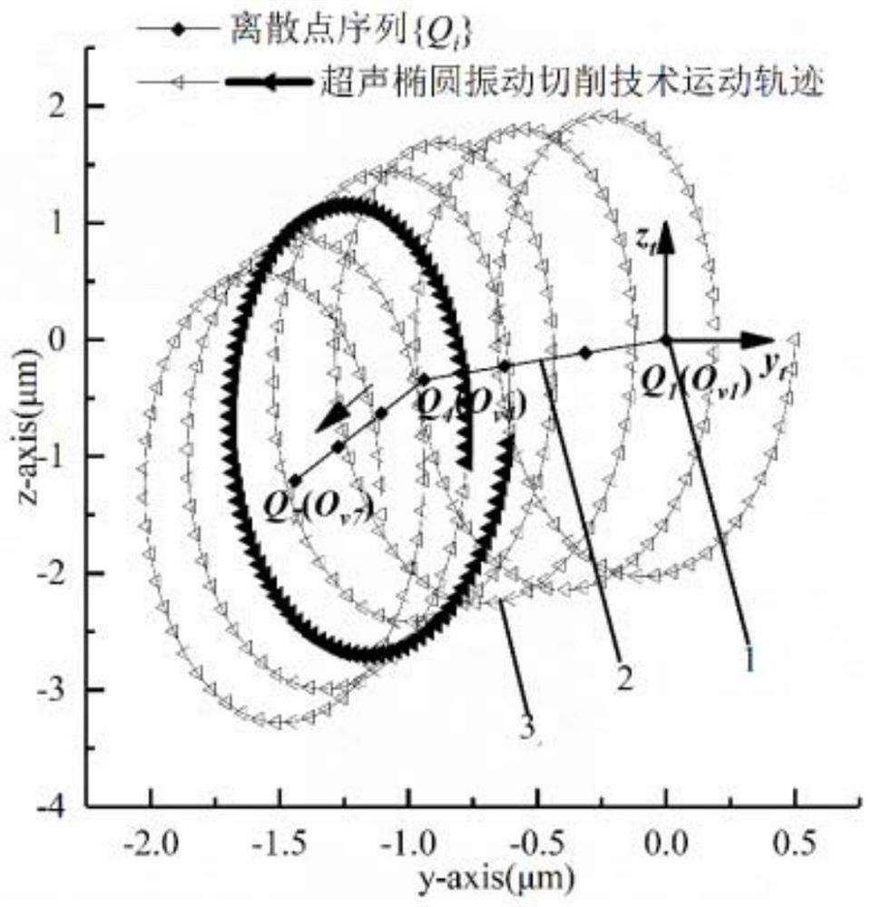
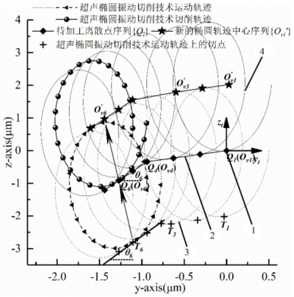
[0079] Specific implementation mode one: combine Figure 1 to Figure 2 Describe this embodiment, a kind of method for calculating the cutting trajectory of ultrasonic elliptical vibration cutting technology in this embodiment, it comprises the following steps:
[0080] Step 1: Discrete the curve to be processed, and obtain a discrete point sequence Q whose distance between two adjacent points is not greater than 0.5 μm i (y i ,z i )(i=1,2,…,n)1, and then from the discrete point sequence Q to be processed i (y i ,z i )(i=1,2,...,n)(1) extract two adjacent points in turn and calculate the slope k of the formed micro-line segment 2 i , and then get the slope sequence k i (i=1,2,…,n), where k n =k n-1 , the formula for calculating the slope is
[0081]
[0082] In the formula, y i 、y i+1 ,z i and z i+1 Q respectively i and Q i+1 The y-coordinate and z-coordinate of ;
[0083] Step 2: Create a sequence of discrete points Q i (y i ,z i )(i=1,2,...,n)1 correspon...
specific Embodiment approach 2
[0103] Specific implementation mode two: combination Figure 3 to Figure 4 To illustrate this embodiment, the calculation method of the motion trajectory 3 of the ultrasonic elliptical vibration cutting technology in step 2 of this embodiment is as follows:
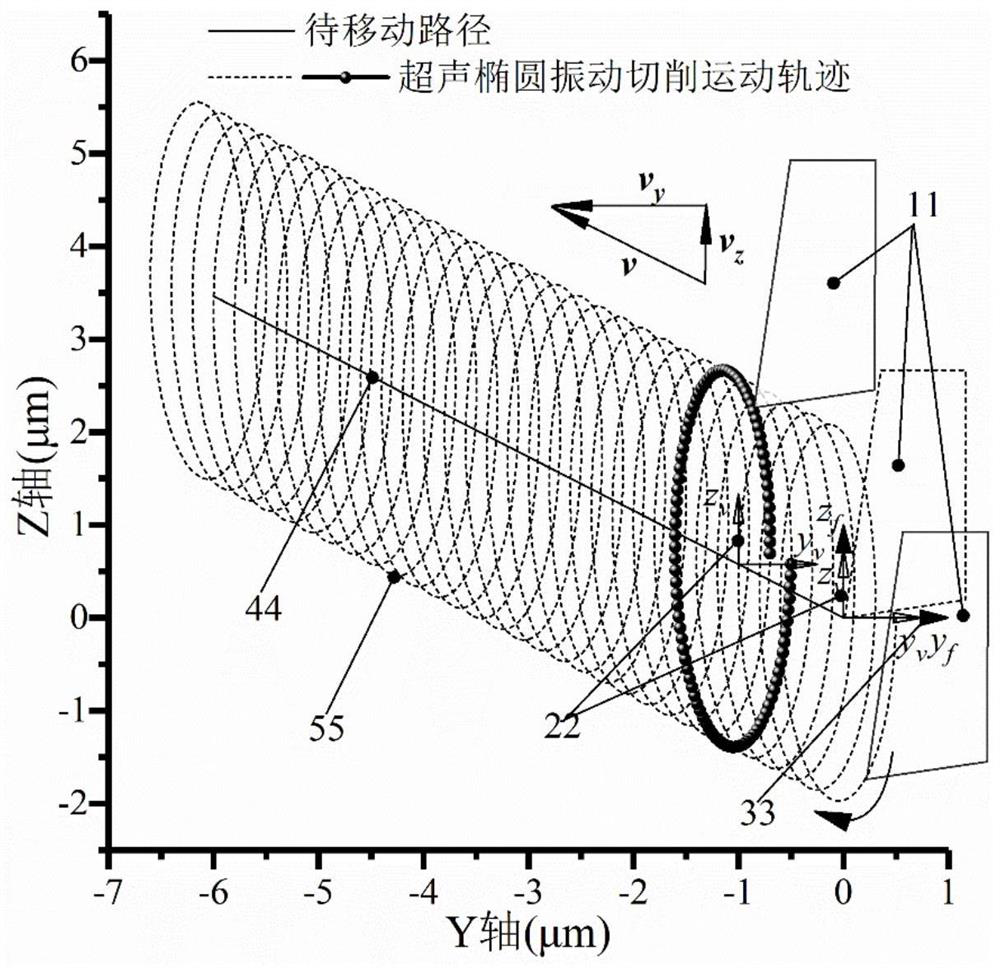
[0104]Step 21: Use the method of homogeneous coordinate transformation to study the motion trajectory expression of the ultrasonic elliptical vibration cutting technology corresponding to the oblique straight line from a new perspective. The main body of the ultrasonic elliptical vibration cutting device is composed of a piezoelectric ceramic sheet group, a horn and a cutter 11. Under the electric excitation of a certain frequency, the piezoelectric ceramic sheet group produces a displacement output with the same frequency as the electric excitation, and the displacement output is amplified by the horn to make the cutter 11 move along a certain path. When the frequency of electrical excitation is the natural frequency of...
specific Embodiment approach 3
[0129] Specific implementation mode three: combination image 3 with Figure 4 To illustrate this embodiment, the motion trajectory method of the ultrasonic elliptical vibration cutting technology proposed in this embodiment is applicable to different types and forms of ultrasonic elliptical vibration cutting devices. The ultrasonic elliptical vibration cutting device described in step 1 is a non-resonance type or a resonance type, and the resonance type is a longitudinal vibration-flexural vibration composite form or a bending vibration-flexural vibration composite form or a longitudinal vibration-longitudinal vibration composite form. It is also applicable to other forms of the non-resonant type and the resonant type, such as bending vibration-bending vibration combination, longitudinal vibration-longitudinal vibration combination, etc. Although the ultrasonic elliptical vibration cutting devices are not the same, their internal movement track synthesis principle is the sam...
PUM
 Abstract
Description
Claims
Application Information
 - R&D
- Intellectual Property
- Life Sciences
- Materials
- Tech Scout
- Unparalleled Data Quality
- Higher Quality Content
- 60% Fewer Hallucinations
Browse by: Latest US Patents, China's latest patents, Technical Efficacy Thesaurus, Application Domain, Technology Topic, Popular Technical Reports.
© 2025 PatSnap. All rights reserved.Legal|Privacy policy|Modern Slavery Act Transparency Statement|Sitemap|About US| Contact US: help@patsnap.com


