Driving shaft and control rod water pressure driving system

A drive shaft and control rod technology, applied in the field of nuclear reactor engineering, can solve problems such as troubled technicians

Active Publication Date: 2020-11-03
TSINGHUA UNIV
View PDF4 Cites 0 Cited by
  • Summary
  • Abstract
  • Description
  • Claims
  • Application Information

AI Technical Summary

Problems solved by technology

How to design the structure of the drive shaft to solve the above problems and realize the engineering application of the control rod bu

Method used


Image

  • Driving shaft and control rod water pressure driving system
  • Driving shaft and control rod water pressure driving system
  • Driving shaft and control rod water pressure driving system

Examples


Embodiment Construction

[0058] Embodiments of the present invention will be further described in detail below in conjunction with the accompanying drawings and examples. The following examples are used to illustrate the present invention, but should not be used to limit the scope of the present invention.

[0059] In the description of the embodiments of the present invention, it should be noted that the terms "center", "longitudinal", "transverse", "upper", "lower", "front", "rear", "left", "right" , "vertical", "horizontal", "top", "bottom", "inner", "outer" and other indicated orientations or positional relationships are based on the orientations or positional relationships shown in the drawings, and are only for the convenience of describing this The embodiments and simplified descriptions of the invention do not indicate or imply that the devices or elements referred to must have a specific orientation, be constructed and operate in a specific orientation, and therefore should not be construed a...


PUM


Abstract

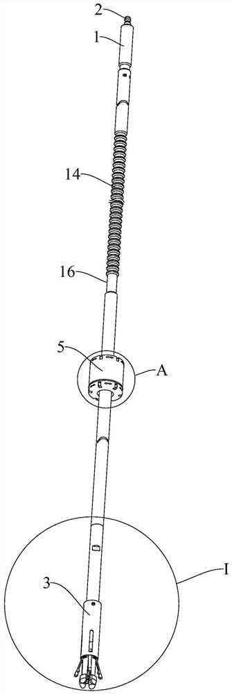
The invention relates to the technical field of nuclear reactor engineering, and provides a driving shaft and a control rod water pressure driving system. The driving shaft comprises an outer shaft, ashaft core and a connecting device, the outer shaft comprises a clamping groove section, the shaft core is arranged in the outer shaft, and the shaft core is suitable for moving in the axial direction of the outer shaft; the connecting device comprises a connecting piece connected to the lower end of the outer shaft and a moving piece connected to the lower end of the shaft core, a plurality of clamping pieces are connected to the connecting piece, and the shaft core drives the moving piece to move along the outer shaft so as to drive the multiple clamping pieces to be switched between a mutually-tightened clamping position and a mutually-away opening position. According to the driving shaft and the control rod water pressure driving system, the outer shaft, the shaft core and the connecting device are arranged, the connecting device can be driven to act through movement of the shaft core, the connecting device and a control rod can be disassembled and assembled, the requirements forlong-distance butt joint and long-distance disassembly and assembly of the control rod and the driving shaft in the reactor refueling state are met, and technical support is provided for refueling operation of a reactor.

Description

technical field [0001] The invention relates to the technical field of nuclear reactor engineering, in particular to a drive shaft and control rod hydraulic drive system. Background technique [0002] Nuclear reactor control rod hydraulic drive technology is a built-in control rod drive technology. Its drive mechanism is placed in the high temperature, high pressure and irradiation environment in the reactor pressure vessel, and it is driven sequentially by three hydraulic cylinders of lifting, transferring and clamping. Transfer and clamp the movement of two sets of control rod assemblies to realize the step-up, step-down and rod-drop functions of the control rod assemblies. [0003] Based on the working principle of the drive mechanism and the structural characteristics of the control rods of advanced small water reactors with a thermal power of 50-300MW, the structure of the drive shaft not only needs to match the action of the pin claw mechanism of the drive mechanism, b...

Claims


Application Information

Patent Timeline
IPC IPC(8): G21C7/12G21C7/16G21C19/06
CPCG21C7/12G21C7/16G21C19/06Y02E30/30
Inventor 薄涵亮王大中姜胜耀赵陈儒秦本科王金海刘潜峰
Owner TSINGHUA UNIV
Why Eureka
Try Eureka