Control rod clamping structure and built-in control rod driving mechanism

A clamping structure and control rod technology, applied in the control of nuclear reactions, climate sustainability, reactor fuel elements, etc., can solve the position deviation, pin claws are difficult to accurately grasp the control rod drive shaft, and the control rod drive shaft moves Accuracy adverse effects and other issues, to achieve the effect of accurate claw position

Pending Publication Date: 2020-11-03
TSINGHUA UNIV
View PDF0 Cites 0 Cited by
  • Summary
  • Abstract
  • Description
  • Claims
  • Application Information

AI Technical Summary

Problems solved by technology

[0005] For this reason, the present invention proposes a control rod clamping structure to solve the problems of parts processing and assembly errors and position deviations between the existing pin claws and hydraulic cylinders, which cause the pin claws to be in the positi

Method used


Image

  • Control rod clamping structure and built-in control rod driving mechanism
  • Control rod clamping structure and built-in control rod driving mechanism
  • Control rod clamping structure and built-in control rod driving mechanism

Examples


Embodiment Construction

[0037] Embodiments of the present invention will be further described in detail below in conjunction with the accompanying drawings and examples. The following examples are used to illustrate the present invention, but should not be used to limit the scope of the present invention.

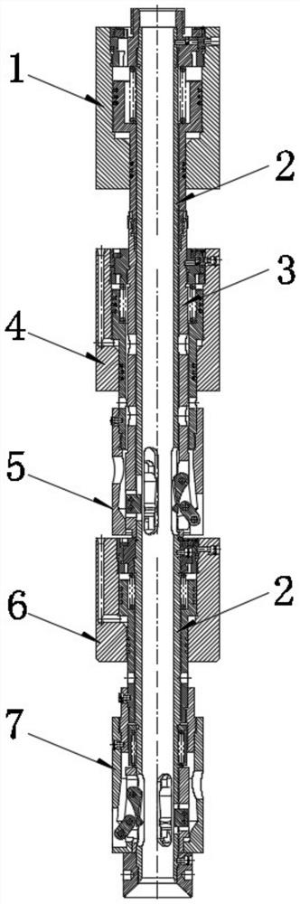
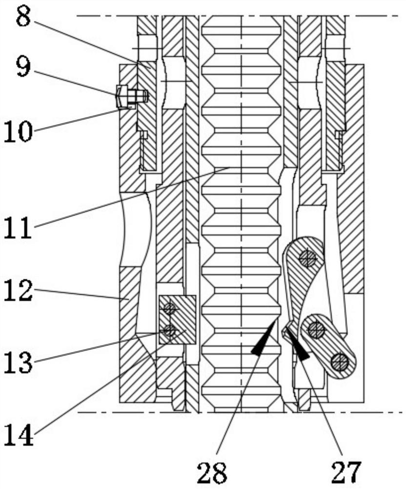
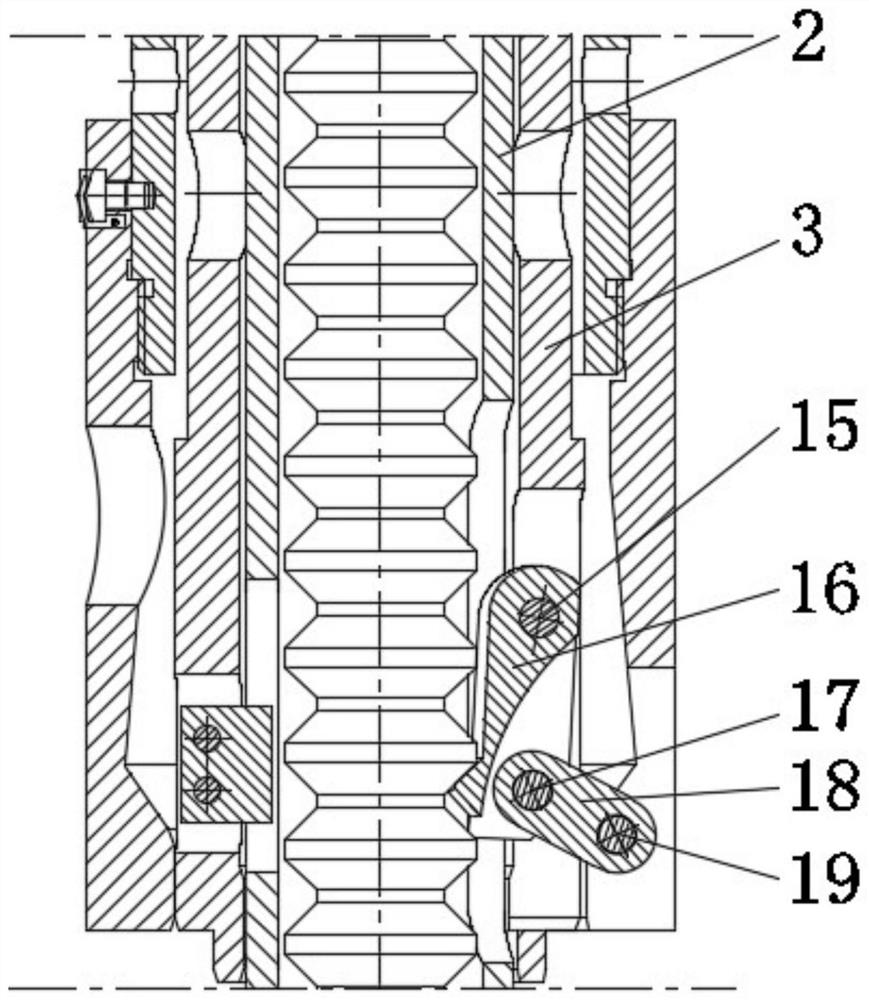
[0038] Such as Figure 1 to Figure 11 As shown, the embodiment of the present invention provides a control rod clamping structure (the embodiment of the present invention is referred to as "structure" for short), and based on this structure, a built-in control rod driving mechanism is provided (the embodiment of the present invention is referred to as "structure" for short). Drive mechanism").

[0039] Such as figure 1 As shown, the structure includes an inner sleeve 2, a positioning mechanism and a claw mechanism. The inner sleeve 2 is used to pass through the shaft holes of several groups of hydraulic cylinders. The inner sleeve 2 is provided with a channel for the control rod drive shaft 11 ...


PUM


Abstract

The invention relates to the technical field of nuclear reactor control rod water pressure driving equipment, in particular to a control rod clamping structure and a driving mechanism provided with the same. The control rod clamping structure comprises an inner sleeve, a positioning mechanism and a pin claw mechanism, the inner sleeve is used for being arranged in shaft holes of a plurality of sets of hydraulic cylinders in a penetrating mode, a channel used for allowing a control rod driving shaft to move in the axial direction is formed in the inner sleeve, the inner sleeve is sequentially provided with at least two installation positions in the axial direction, and the hydraulic cylinders are arranged between the adjacent installation positions; at least one group of pin claw mechanismsand at least one group of positioning mechanisms are mounted on each installation position, the pin claw mechanisms are used for clamping and driving the control rod driving shaft to move, and a preset angle is formed between the adjacent pin claw mechanisms and positioning mechanisms. Abrasion to the control rod driving shaft during grabbing and moving can be reduced, and adverse effects of errors of part machining and assembling and position deviation on the moving accuracy of the control rod driving shaft can be eliminated.

Description

technical field [0001] The invention relates to the technical field of nuclear reactor control rod hydraulic driving equipment, in particular to a control rod clamping structure and a built-in control rod driving mechanism. Background technique [0002] Nuclear reactor control rod driving mechanism, referred to as the driving mechanism, is the most critical safety equipment of the reactor, and is responsible for important functions such as starting, power regulation and shutdown of the reactor. According to the installation position of the control rods, the control rod drive mechanism can be divided into an external control rod drive mechanism and an internal control rod drive mechanism. Among them, the nuclear reactor control rod hydraulic driving system is a built-in control rod driving mechanism. The driving mechanism is placed in the high temperature, high pressure and irradiation environment in the reactor pressure vessel. Sequentially drive transmission, clamp two set...

Claims


Application Information

Patent Timeline
IPC IPC(8): G21C19/06G21C7/16
CPCG21C7/16G21C19/06Y02E30/30
Inventor 薄涵亮王大中张作义秦本科赵陈儒刘潜峰王金海
Owner TSINGHUA UNIV
Why Eureka
Try Eureka