
A rotating vibrator mounting base

A rotating and fixed seat technology, applied in the direction of antenna support/mounting device, antenna, antenna parts, etc., can solve the problems of affecting the reliability of the antenna, low installation efficiency, high material cost, etc., and achieve no hidden danger of passive intermodulation , The structure is stable and reliable, and the effect of avoiding direct contact

Active Publication Date: 2021-12-10
GUANGDONG BROADRADIO COMM TECH
View PDF7 Cites 0 Cited by
  • Summary
  • Abstract
  • Description
  • Claims
  • Application Information

AI Technical Summary

Problems solved by technology

There are two main ways to connect the plastic holder and the reflector. One is to fasten the plastic holder and the reflector with multiple screws or rivets. The connection reliability is high, but the installation efficiency is extremely low, and it makes the The material cost is relatively high; secondly, an elastic buckle is set on the plastic holder, and the installation hole of the reflector is snapped and matched through the base hole-base shaft, so that the installation efficiency is improved. For example, the patent name is "a die-casting Vibrator fixed clip" (application number CN201820043916) is an example of this connection method, but this patent also has some disadvantages: first, the solution consists of four buckle bodies distributed in a central circular array and connected to the reflector. There is a certain relative distance between the four buckle bodies. In engineering practice, it is often necessary to press the buckle bodies several times to complete the installation operation of the four buckle bodies. Compared with the fastening of screws or rivets Although the connection method and operating efficiency have been improved, there is still room for improvement
In addition, the buckle body and the reflector are matched through the base hole-base shaft. Under the aging effect of temperature and humidity changes in the working condition, there is a certain risk of tripping failure due to the deformation of the elastic buckle, which will affect the reliability of the antenna.

Method used


Image

  • A rotating vibrator mounting base
  • A rotating vibrator mounting base
  • A rotating vibrator mounting base

Examples


Embodiment Construction

[0028] In order to make the purpose, technical solutions and advantages of the embodiments of the present invention clearer, the technical solutions in the embodiments of the present invention will be clearly and completely described below in conjunction with the drawings in the embodiments of the present invention. Obviously, the described embodiments It is a part of embodiments of the present invention, but not all embodiments. These drawings are all simplified schematic diagrams, and only illustrate the basic structure of the present invention in a schematic manner, so the drawings only show the configurations related to the present invention. Based on the embodiments of the present invention, all other embodiments obtained by persons of ordinary skill in the art without making creative efforts belong to the protection scope of the present invention.

[0029] It should be noted that when an element is referred to as being “mounted on” another element, it can be directly on ...


PUM


Abstract

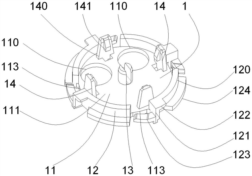
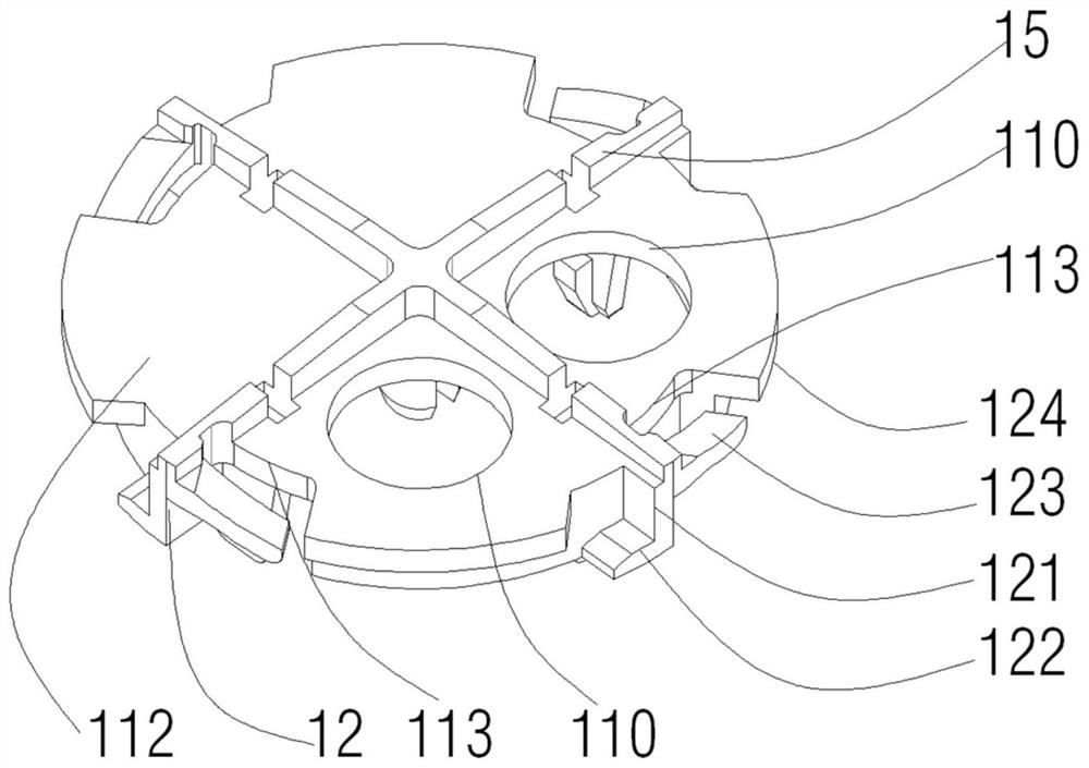
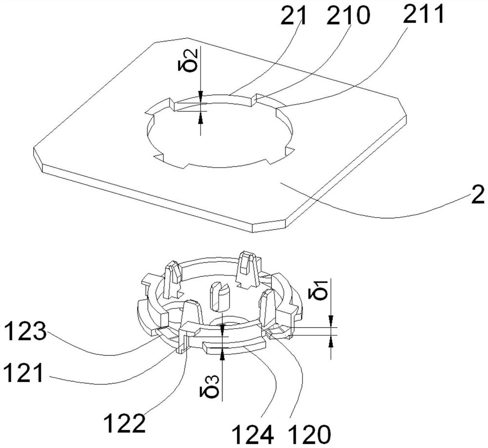
The present invention relates to the technical field of wireless communication, and in particular to a rotating vibrator installation and fixing seat, which is used to fix the vibrator on a reflector, including a body, and the body includes an upper mounting surface, a lower mounting surface and a side ring set opposite to each other. wall; the side ring wall is provided with a limit structure for connecting with the reflector; the upper mounting surface is provided with a buckle and a positioning column for fixing the vibrator; the limit structure includes a segmented ring, and the side The baffle, the upper baffle, the curved spring arm and the lower baffle. The rotary vibrator installation and fixing seat created by the present invention only needs to perform a small-angle rotation operation to complete the installation of the vibrator installation and fixing seat and the reflector, and the operation is very simple and fast; The external force makes the structure stable and reliable without the risk of failure. The invention also avoids the direct contact between the vibrator and the reflector, so that the performance of the vibrator using the vibrator to install the fixed seat is stable, and there is no hidden danger of passive intermodulation.

Description

technical field [0001] The invention relates to the technical field of wireless communication, in particular to a rotating vibrator mounting and fixing base. Background technique [0002] In the field of mobile communication, as an important part of the base station antenna, the vibrator plays a vital role in the performance of the base station antenna. Therefore, the reliability of the installation of the vibrator unit has a great impact on the overall performance and reliability of the antenna. In addition, with the development of mobile communication technology, the number of antenna dipole units has increased geometrically. The installation and connection of dipoles and reflectors in the overall assembly of the antenna occupies a considerable proportion of time and labor costs. [0003] The method of connecting the vibrator and the reflector through a plastic card holder has become the mainstream solution adopted by the fixed installation of the vibrator in the industry ...

Claims


Application Information

Patent Timeline
Patent Type & Authority Patents(China)
IPC IPC(8): H01Q1/12H01Q1/24H01Q19/10
CPCH01Q1/12H01Q1/246H01Q19/104
Inventor 孙丹吴壁群苏振华张鹏刘德富
Owner GUANGDONG BROADRADIO COMM TECH
Learn More