Dental handpiece lubricator

A dental handpiece and oil filling machine technology, applied in dentistry, dental drilling, medical science, etc., can solve the problems of low efficiency, danger, accidents, etc., and achieve the effect of high oil filling efficiency, easy pressure, and reduced consumption.

Pending Publication Date: 2020-11-06
NINGBO LIFE MEDICAL TECH
View PDF10 Cites 0 Cited by
  • Summary
  • Abstract
  • Description
  • Claims
  • Application Information

AI Technical Summary

Problems solved by technology

[0003] At present, there are two ways of oiling dental handpieces: one is through manual oiling with an oiler, which requires a lot of labor, is inefficient and cannot accurately control the amount of oiling; the other is through an automatic oiling machine. The automatic oiling of the dental handpiece is highly efficient and can achieve a good oiling effect
However, most of the existing automatic lubricating machines use the external air source to fill the oil storage tank with compressed air, and then spray the lubricating oil in the oil storage tank into the dental handpiece through the compressed air; when the oil storage tank is filled with compressed air, its internal The pressure is high, and if the fuel tank cap is not firmly connected, it is easy to cause danger and accidents; in addition, the oiling effect of this method is not ideal, and it is easy to cause a waste of dental handpiece lubricating oil

Method used


Image

  • Dental handpiece lubricator
  • Dental handpiece lubricator
  • Dental handpiece lubricator

Examples


Embodiment Construction

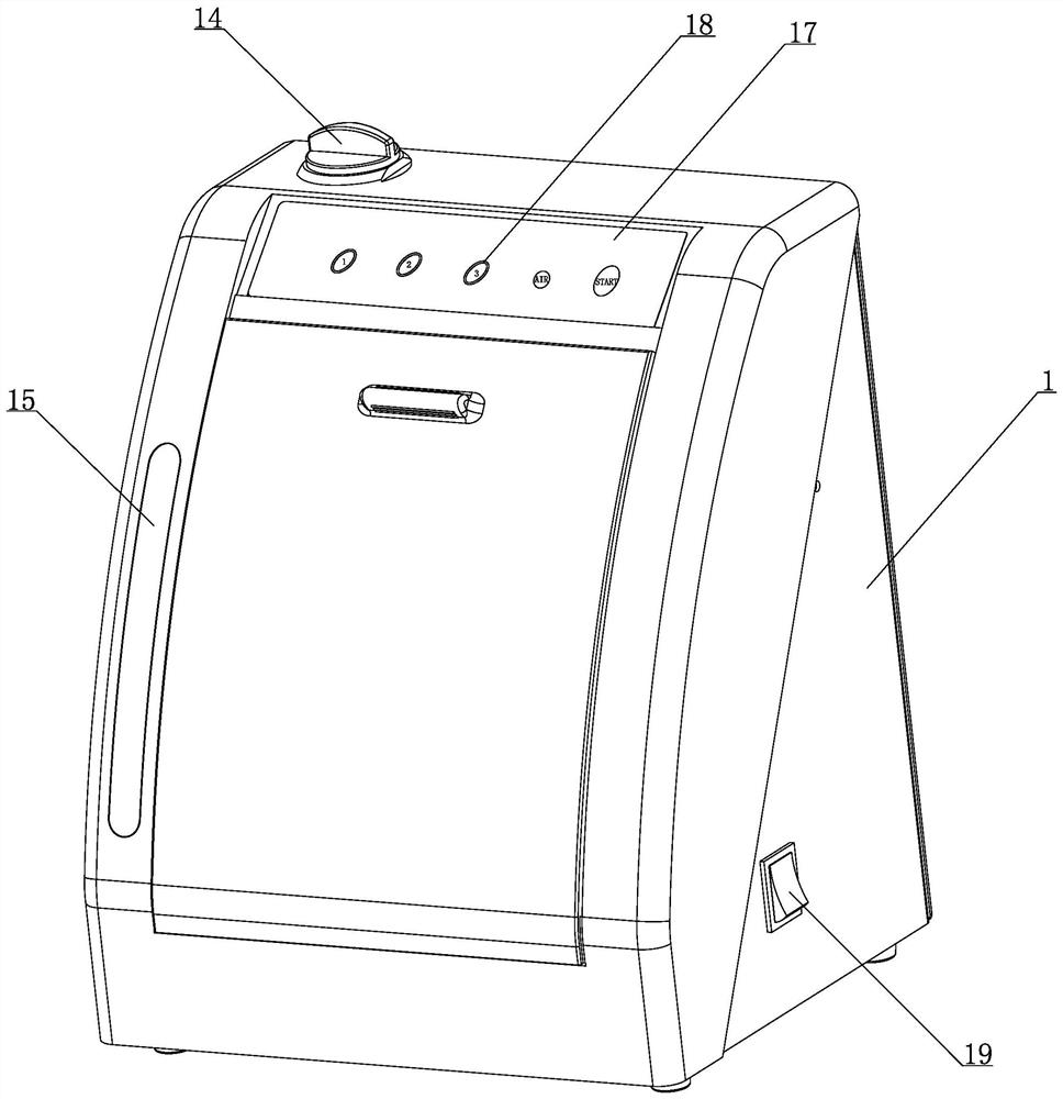
[0022] The present invention will be further described in detail below with reference to the drawings and specific embodiments.

[0023] In the description of the present invention, it should be understood that the terms "upper", "lower", "front", "rear", "left", "right", "vertical", "horizontal", "top", The orientation or positional relationship indicated by "bottom", "inner", "outer", etc. is based on the orientation or positional relationship shown in the drawings, and is only for the convenience of describing the present invention and simplifying the description, rather than indicating or implying the device or The element must have a specific orientation, be constructed and operated in a specific orientation, and therefore cannot be understood as a limitation of the present invention. At the same time, the terms "first", "second", etc. are only used to distinguish the names of various components, and there is no primary-secondary relationship, so they cannot be understood as...


PUM


Abstract

The invention provides a dental handpiece lubricator with the following structure that: the dental handpiece lubricator comprises a shell and at least one handpiece joint; a lubricating mechanism, a gas inlet mechanism and a communicating part with a mixing chamber are arranged in the shell; the handpiece joint is communicated with the mixing chamber of the communicating part by a connecting pipe;and the lubricating mechanism and the gas inlet mechanism are used for pumping a gas-oil mixture into the mixing chamber of the communicating part. The communicating part with the mixing chamber is arranged in the shell, oil is pumped into the mixing chamber by an oil pump, and meanwhile, gas is controlled by a gas inlet valve to enter the mixing chamber, so that lubricating oil and the air are sufficiently mixed and oil mist is formed; and a dental handpiece can be more sufficiently lubricated, lubricating efficiency is higher, and consumption of the lubricating oil can be reduced so as to achieve an effect of saving the oil. In addition, the lubricating mechanism and the gas inlet mechanism are separately arranged, so that compressed air does not need to be filled in an oil storage box,the pressure is also easier to control, and the dental handpiece lubricator is safer to use.

Description

Technical field [0001] The invention relates to the technical field of dental medical equipment, in particular to a dental handpiece oiler. Background technique [0002] In order to prolong the service life of the dental handpiece and prevent cross-infection of oral diseases, the dental handpiece after use needs to be cleaned, dried and oiled. In the daily maintenance of the dental handpiece, oiling the dental handpiece is an indispensable step, which can prolong the service life of the dental handpiece and keep the dental handpiece in good working condition. [0003] At present, there are two oil injection methods for dental handpieces: one is to inject oil manually with an oiler, which requires a lot of labor, is inefficient and cannot accurately control the amount of oil; the other is to achieve by automatic oiler The automatic oiling of dental handpieces has high efficiency and can achieve good oiling effects. However, most of the existing automatic lubricating machines use t...

Claims


Application Information

Patent Timeline
IPC IPC(8): A61C1/00
CPCA61C1/0084
Inventor 鲁立辉沈远业郑科杰
Owner NINGBO LIFE MEDICAL TECH
Why Eureka
Try Eureka