Horizontal flue type demister

A horizontal flue and mist eliminator technology, which is applied in chemical instruments and methods, gas treatment, and dispersed particle separation, etc., can solve the problem of limited demisting effect of corrugated plates, limited mist condensation effect, unfavorable horizontal flue type mist eliminator Promote the use of other issues to achieve the effect of improving the capture effect and improving the effect of defogging

Inactive Publication Date: 2020-11-06
澳斯意环保工程(苏州)有限公司
View PDF6 Cites 1 Cited by
  • Summary
  • Abstract
  • Description
  • Claims
  • Application Information

AI Technical Summary

Problems solved by technology

[0003] When the current horizontal flue type demister is in use, the gas and liquid in the mist are often separated only through the cooperation of multiple sets of corrugated plates, but the condensation effect of the mist is very limited only by the corrugated plates themselves, thus It is impossible to further improve the use effect of the whole horizontal flue type mist eliminator, which is not conducive to the popularization and use of the horizontal flue type mist eliminator. The corrugated plates collide to make the mist gradually gather on the corrugated plates to form larger water droplets, and then use the gravity of the water droplets themselves to make the water droplets fall, but the defogging effect of the corrugated plates in this way is very limited , it is impossible to further increase the falling speed of the fog beads on the corrugated plate, thus limiting the demisting efficiency of the entire demister

Method used


Image

  • Horizontal flue type demister
  • Horizontal flue type demister
  • Horizontal flue type demister

Examples


Embodiment 1

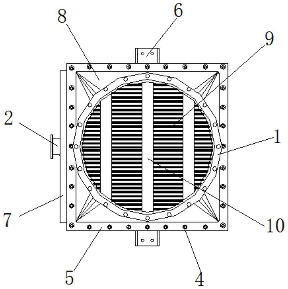
[0029] Example 1, such as Figure 4 , 5As shown in and 7, when the mist passes between multiple sets of screens A902, a part of the mist will gradually adhere after touching the surface of the screen A902, and a part of the mist will gradually adhere when it touches the inner side of the arc-shaped groove 903 On the inner side wall of the arc-shaped groove 903, another part of the mist touches the surface of the interlaced screen B904, is caught by the through holes on the surface of the screen B904, and a part of the mist adheres when passing through multiple sets of auxiliary rods 13. On the surface of the auxiliary rod 13, when the fog beads attached to the surface of the auxiliary rod 13, the corrugated plate 901, the screen A902, the arc groove 903 and the screen B904 gradually collide and increase, under the influence of gravity, the heavier fog beads Will gradually flow downwards, thereby flowing into the bottom of the square bin 3.

Embodiment 2

[0030] Example 2, such as Figure 4 , 5 , 7 and 8, when the defogged flowing air passes through the square bin 3, the four sets of fan blades 113 are blown to rotate, thereby driving the collar 112 to rotate. Also constantly rotate, when spheroid 116 moved on the arc projection 115, articulated rod 118 was jacked up gradually, and spring 117 was stressed and shortened, after spheroid 116 lost contact with arc projection 115, due to spring 117 elastic recovery force, forcing the end of the hinged rod 118 close to the ball 116 to quickly hit the surface of the collar 112 to produce a knocking effect, and the vibration generated by the knocking is transmitted to the multiple groups of screens A902 through the connecting frame B12, so that it is attached to the surface of the screen A902 The mist beads gather quickly due to vibration and flow downward when they are small.

[0031] Working principle: Before use, connect one end of the square chamber 3 with the mist supply device ...


PUM


Abstract

The invention discloses a horizontal flue type demister. The horizontal flue type demister includes a square bin, conical pipes are symmetrically arranged at two ends of the square bin, flange platesB are symmetrically arranged at the ends, close to each other, of the outer sides of the conical pipes and the square bin, bolts are evenly arranged on the outer sides of the flange plates B in a threaded mode, the two adjacent groups of flange plates B are fixedly connected through the bolts, three sets of connecting frames A are arranged at one end in the square bin, three sets of connecting frames B are arranged at the other end in the square bin, and knocking assemblies are arranged in the middles of the connecting frames B. According to the invention, joints, the square bin, a demisting assembly, the connecting frames A, the knocking assemblies and the connecting frames B are matched for use, vibration generated by knocking is transmitted to the multiple sets of screens A through theconnecting frames B, and fog beads attached to the surfaces of the screens A are rapidly gathered and flow downwards due to vibration when the fog beads are small, therefore the demisting efficiency of the whole device is greatly improved, and the demisting effect of the demister is improved.

Description

technical field [0001] The invention relates to the technical field of mist removal equipment, in particular to a horizontal flue type mist eliminator. Background technique [0002] When the gas containing mist needs to be separated from the gas and liquid, it is often necessary to use a demister. Due to the inertial impact of the gas, the mist collides with the corrugated plate and the droplets that are gathered are so large that the gravity generated by itself exceeds that of the gas. When the resultant force of the rising force of the liquid and the surface tension of the liquid, the droplet is separated from the surface of the corrugated plate, and the separation of gas and liquid is realized. [0003] When the current horizontal flue type demister is in use, the gas and liquid in the mist are often separated only through the cooperation of multiple sets of corrugated plates, but the condensation effect of the mist is very limited only by the corrugated plates themselves...

Claims


Application Information

Patent Timeline
Patent Type & Authority Applications(China)
IPC IPC(8): B01D46/12B01D46/00B01D46/42
CPCB01D46/0053B01D46/12B01D46/4227B01D2257/80B01D2258/0283
Inventor 张显磊周文祥
Owner 澳斯意环保工程(苏州)有限公司
Why Eureka
Try Eureka