Thin bamboo strip burr removing equipment for bamboo basket weaving
A strip and burr technology is applied in the field of strip burr removal equipment for bamboo basket weaving, which can solve the problems of low work efficiency and labor, and achieve the effect of high work efficiency.
- Summary
- Abstract
- Description
- Claims
- Application Information
AI Technical Summary
Problems solved by technology
Method used
Image

Examples
Embodiment 1
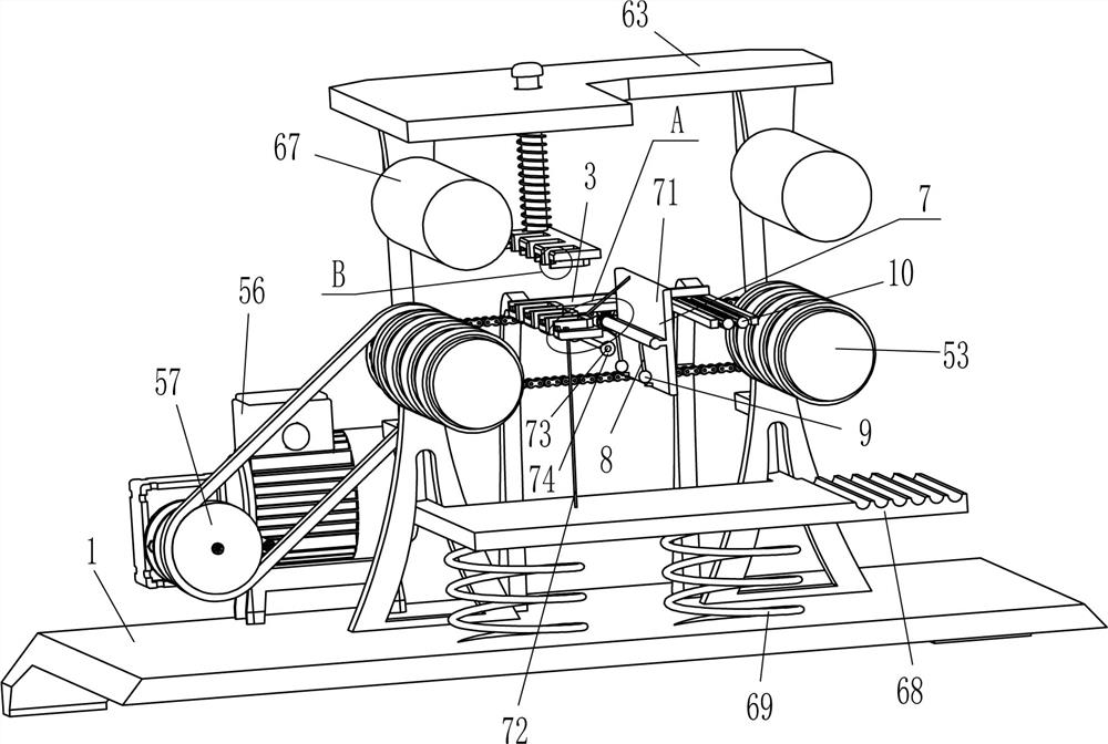
[0024] A kind of equipment for removing raw edges of strips for bamboo basket weaving, such as Figure 1-Figure 5 As shown, it includes a base 1, a support rod 2, a u-shaped plate 3, a fixed scraper 4, a conveying mechanism 5, and a scraping mechanism 6. Two support rods 2 and four support rods are fixedly connected to the front and rear sides of the top of the base 1. 2 A U-shaped plate 3 is fixedly connected between the inner ends, and two fixed scrapers 4 of different sizes are fixedly connected to the front and rear left sides of the groove of the U-shaped plate 3. The fixed scrapers 4 of different sizes cooperate with each other, and the base 1 There is a conveying mechanism 5 on the top, and the u-shaped plate 3 is located between the conveying mechanisms 5 to cooperate with it. A scraping mechanism 6 is arranged between the conveying mechanism 5 and the top of the base 1. 6 also cooperates with conveying mechanism 5.
[0025] The conveying mechanism 5 includes a suppor...
Embodiment 2
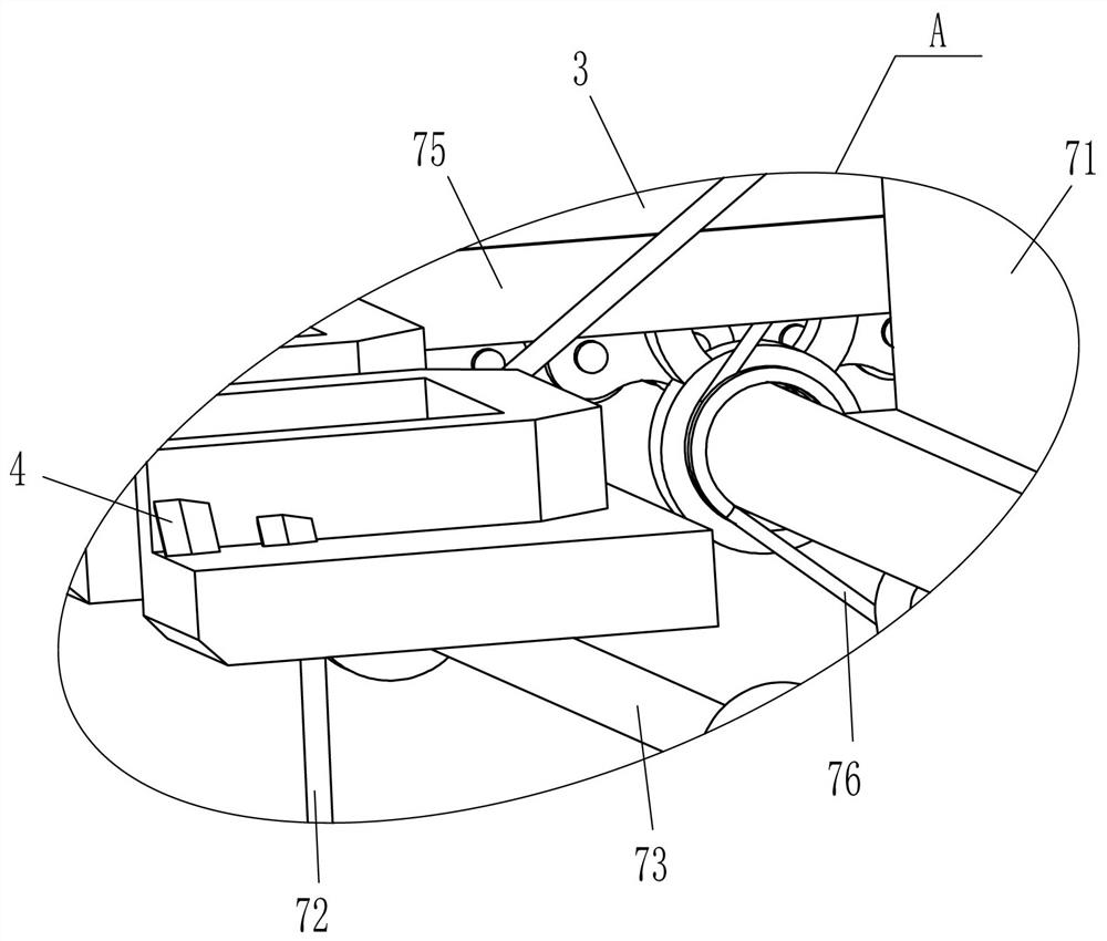
[0031] On the basis of Example 1, such as figure 2 , image 3 with Figure 5 As shown, guide mechanism 7 is also included, and guide mechanism 7 includes swing plate 71, backguy 72, rotating rod 73, guide wheel 74 and torsion spring 76, and u-shaped plate 3 middle part has opening 75, and u-shaped plate 3 outer bottoms The middle rotating type is connected with a swing plate 71, and the swing plate 71 passes through the opening 75 to cooperate with it. The hinge of the swing plate 71 and the U-shaped plate 3 is connected with a torsion spring 76, and the front and back of the left side of the swing plate 71 is symmetrically connected with a backguy 72. The left side of the outer bottom of the u-shaped plate 3 is connected with a rotating rod 73, and the front and rear sides of the rotating rod 73 are fixedly connected with a guide wheel 74, and the tail end of the backguy 72 is fixed around the guide wheel 74 and the top left side of the pedal 68. connect.
[0032] When fi...
Embodiment 3
[0034] On the basis of embodiment 1 and embodiment 2, such as figure 2 with Figure 5 As shown, it also includes u-shaped rods 8 and rolling balls 9, three u-shaped rods 8 are evenly spaced on the lower part of the left side of the swing plate 71, and the sliding type is provided with rolling balls 9 on the u-shaped rods 8.
[0035] It also includes friction rollers 10, two friction rollers 10 are rotationally connected to the bottom right side of the u-shaped plate 3.
[0036] When the oscillating plate 71 reverses and is in a horizontal state, the oscillating plate 71 drives the rolling ball 9 to slide through the u-shaped rod 8, and then when the oscillating plate 71 forwardly rotates and resets, the oscillating plate 71 drives the rolling ball 9 to slide and reset, and the rolling ball 9 resets through u The molded rod 8 vibrates the swing plate 71 . In this way, all the sawdust on the oscillating plate 71 can be dropped to avoid residues.
[0037] When the operator pl...
PUM
 Abstract
Description
Claims
Application Information
 - Generate Ideas
- Intellectual Property
- Life Sciences
- Materials
- Tech Scout
- Unparalleled Data Quality
- Higher Quality Content
- 60% Fewer Hallucinations
Browse by: Latest US Patents, China's latest patents, Technical Efficacy Thesaurus, Application Domain, Technology Topic, Popular Technical Reports.
© 2025 PatSnap. All rights reserved.Legal|Privacy policy|Modern Slavery Act Transparency Statement|Sitemap|About US| Contact US: help@patsnap.com