
A sponge mop demoulding device

A demoulding device and sponge technology, applied in the field of sponge mop demoulding device, can solve the problems of low demoulding efficiency, time-consuming and laborious, etc., and achieve the effects of improving demoulding efficiency, expanding the scope of application, and saving time

Active Publication Date: 2022-05-27
盐城永盛海绵制品有限公司
View PDF6 Cites 1 Cited by
  • Summary
  • Abstract
  • Description
  • Claims
  • Application Information

AI Technical Summary

Problems solved by technology

[0004] In order to overcome the disadvantages of time-consuming and labor-intensive demoulding and low demoulding efficiency, the technical problem is to provide a sponge mop demoulding device that saves time and labor, improves demoulding efficiency, and can adapt to sponge mop molds of different heights

Method used


Image

  • A sponge mop demoulding device
  • A sponge mop demoulding device
  • A sponge mop demoulding device

Examples


Embodiment 1

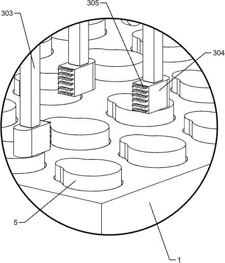
[0024] A sponge mop demoulding device, such as Figure 1-2 As shown, it includes a sponge mop mold 1, an adjustment mechanism 2 and a demoulding mechanism 3, the sponge mop mold 1 is used for the forming of the sponge mop body 5, and the sponge mop mold 1 is placed on the ground on the left and right sides. The adjustment mechanism 2, the adjustment mechanism 2. The upper part is provided with a demoulding mechanism 3, and the demoulding mechanism 3 is located above the sponge mop mold 1.

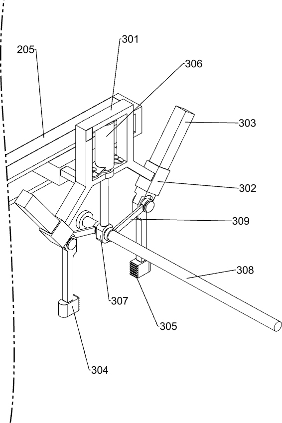
[0025] When the worker uses this equipment to demould the sponge mop body 5 in the sponge mop mold 1, first adjust the adjustment mechanism 2 to a suitable height according to the height of the sponge mop mold 1, and then start the demoulding mechanism 3 to remove the sponge mop. The main body 5 is demolded.

Embodiment 2

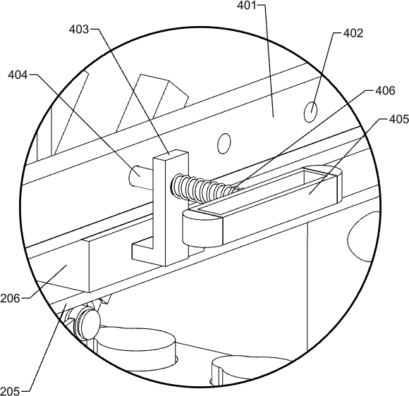
[0027] On the basis of Example 1, as Figure 3-9 As shown, the adjustment mechanism 2 includes a large adjustment plate 201, a small adjustment plate 202, a fixed rod 204, a slide rail 205, a slider 206 and a cross rod 207. Large adjustment plates are placed on the ground on the left and right sides of the sponge mop mold 1. 201, the inside of the large adjustment plate 201 is slidably provided with a small adjustment plate 202, the large adjustment plate 201 is in contact with the small adjustment plate 202, the large adjustment plate 201 and the small adjustment plate 202 are both provided with through holes 203, through holes 203 The shape is circular, the fixing rod 204 can be inserted into the through hole 203, the fixing rod 204 is matched with the through hole 203, the tops of the small adjustment plates 202 on the left and right sides are installed with horizontally arranged sliding rails 205, and the sliding rails 205 slide inside A sliding block 206 is provided in th...


PUM


Abstract

The invention relates to a demoulding device for a mop, in particular to a demoulding device for a sponge mop. The technical problem is: to provide a sponge mop demoulding device which saves time and effort, improves demoulding efficiency, and can adapt to sponge mop molds of different heights. The invention provides such a sponge mop demoulding device, which includes a sponge mop mould, an adjustment mechanism and a demoulding mechanism; the sponge mop mold is evenly equipped with a sponge mop body, and the left and right sides of the sponge mop mold are placed on the ground with adjustment mechanisms , The upper part of the adjustment mechanism is equipped with a demoulding mechanism. The adjustment mechanism can be used to demould the sponge mop molds of different heights, expanding the scope of application of the equipment; the demoulding mechanism can be used to demould the sponge mop body, which can save manpower and improve the efficiency of demoulding; use the limit mechanism , can quickly find a suitable demoulding position, save time and improve the efficiency of demoulding.

Description

technical field [0001] The invention relates to a mop demoulding device, in particular to a sponge mop demoulding device. Background technique [0002] When producing the sponge mop used in people's daily life, it is necessary to pull out the sponge mop body from the sponge mop mold, and then carry out subsequent processing to finally make the finished product we use. When demoulding the sponge mop body, the traditional method is for workers to pull out the sponge mop bodies in the sponge mop mold one by one with a vice. [0003] How to design a sponge mop demoulding device that saves time and effort, improves demoulding efficiency, and can adapt to different heights of sponge mop molds is the main technical problem to be solved by the present invention. SUMMARY OF THE INVENTION [0004] In order to overcome the disadvantages of time-consuming and labor-intensive demolding and low demolding efficiency, the technical problem is to provide a sponge mop demoulding device tha...

Claims


Application Information

Patent Timeline
Patent Type & Authority Patents(China)
IPC IPC(8): B29C44/34B29C33/44
CPCB29C44/34B29C33/44
Inventor 陶玉峰
Owner 盐城永盛海绵制品有限公司
Learn More