Inter-axle differential mechanism structure

A technology of inter-axle differentials and differentials, applied in differential transmissions, belts/chains/gears, mechanical equipment, etc., can solve problems such as consumption, high cost of use, and poor fuel economy

Inactive Publication Date: 2020-11-06
FAW JIEFANG AUTOMOTIVE CO
View PDF6 Cites 3 Cited by
  • Summary
  • Abstract
  • Description
  • Claims
  • Application Information

AI Technical Summary

Problems solved by technology

The double-axle joint drive structure is adopted to increase the driving force of the whole vehicle, but when it is empty or lightly loaded, the driving force of the whole vehicle is excessive, consumes too much energy, and the fuel economy is not good, resulting in high cost of use, and Increased environmental pollution, which is not conducive to the demand for energy conservation and environmental protection

Method used


Image

  • Inter-axle differential mechanism structure
  • Inter-axle differential mechanism structure
  • Inter-axle differential mechanism structure

Examples


Embodiment 1

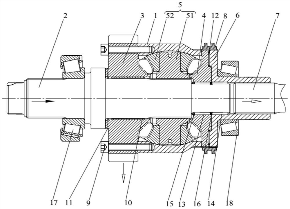
[0046] This embodiment provides an inter-axle differential structure, which is suitable for the field of automobile axles, especially the double-axle joint drive structure of the middle axle drive and the rear axle drive. Such asfigure 1 As shown, the structure of the inter-axle differential includes a differential housing 1, an input shaft 2, an output gear 3, a side gear 4, a transmission gear assembly 5, a bearing bracket 6, an output shaft 7 and a shift fork ring 8, and the differential The transmission housing 1 plays the role of overall support, and the input shaft 2 can also be called a cylindrical gear shaft. The input shaft 2 is passed through the differential housing 1, and the input shaft 2 is the input end of the torque. The output gear 3 is sheathed on the input shaft 2 and connected to one side of the differential case 1 . The output gear 3 is transmission connected to the middle axle, and the torque input from the input shaft 2 is transmitted to the middle axle t...

Embodiment 2

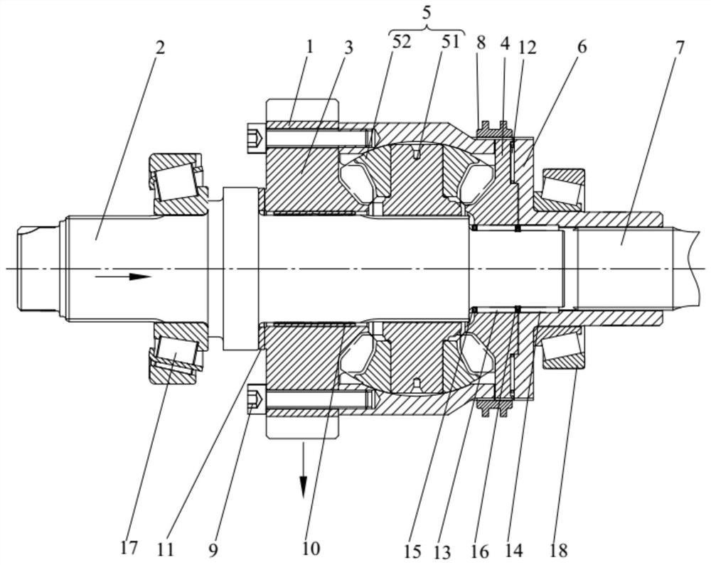
[0065] The structure and working principle of this embodiment and the first embodiment are generally similar, and the only difference lies in the connection mode between the output gear 3 and the differential case 1 . like Figure 4 As shown, in this embodiment, the output gear 3 is provided with a first connecting tooth, and the differential case 1 is provided with a second connecting tooth corresponding to the first connecting tooth, and the first connecting tooth and the second connecting tooth pass through The tooth-embedded structures 19 are connected together, and the first connecting tooth and the second connecting tooth are engaged with each other, and the fixing effect is good.


PUM


Abstract

The invention belongs to the technical field of automobile axles, and discloses an inter-axle differential mechanism structure. According to the inter-axle differential mechanism structure, an input shaft is arranged in a differential mechanism shell in a penetrating mode; an output gear is arranged on the input shaft in a sleeving mode and connected to one side of the differential mechanism shell, and the output gear is in transmission connection with a middle axle; a half shaft gear is arranged on the input shaft in a sleeving mode and connected with the differential mechanism shell; a transmission gear assembly is arranged inside the differential mechanism shell and arranged on the input shaft in a sleeving mode, and the transmission gear assembly is engaged with the output gear and thehalf shaft gear; a bearing support is arranged on the input shaft in a sleeving mode and connected with the half shaft gear; and the output shaft is arranged in the bearing support in a penetrating mode and is connected with the bearing support, the output shaft is in transmission connection with a rear axle, and a shift fork ring is configured to slide among and selectively be connected with thedifferential mechanism shell, the half shaft gear and the bearing support. The inter-axle differential mechanism structure is driven by a single axle when no load exists, the energy consumption is reduced, the fuel economy is improved, and the energy-saving and environment-friendly requirements are facilitated.

Description

technical field [0001] The invention relates to the technical field of automobile axles, in particular to a structure of an inter-axle differential. Background technique [0002] In the domestic heavy-duty commercial vehicles, the double-axle joint drive structure of the middle axle drive and the rear axle drive is mostly used. This type of drive axle adopts an inter-axle differential structure, which is used to adjust the speed difference between the middle axle and the rear axle to prevent the middle axle or the rear axle from slipping. The double-axle joint drive structure is adopted to increase the driving force of the whole vehicle, but when it is empty or lightly loaded, the driving force of the whole vehicle is excessive, consumes too much energy, and the fuel economy is not good, resulting in high cost of use, and Increased environmental pollution is not conducive to the demand for energy saving and environmental protection. Contents of the invention [0003] The...

Claims


Application Information

Patent Timeline
Patent Type & Authority Applications(China)
IPC IPC(8): F16H48/06F16H48/38F16H48/40F16H48/42
CPCF16H48/06F16H48/38F16H48/40F16H48/42F16H2048/423
Inventor 冯涛姜雷王林国
Owner FAW JIEFANG AUTOMOTIVE CO
Why Eureka
Try Eureka