

Air-conditioning cooling system based on building structure
A technology of air-conditioning and cold air, which is applied in the field of air-conditioning and cooling, and can solve problems such as the inability to exchange the air inside the building with the air outside the building, and achieve the effect of avoiding discomfort
- Summary
- Abstract
- Description
- Claims
- Application Information
AI Technical Summary
Problems solved by technology
Method used
Image

Examples
specific Embodiment approach 1
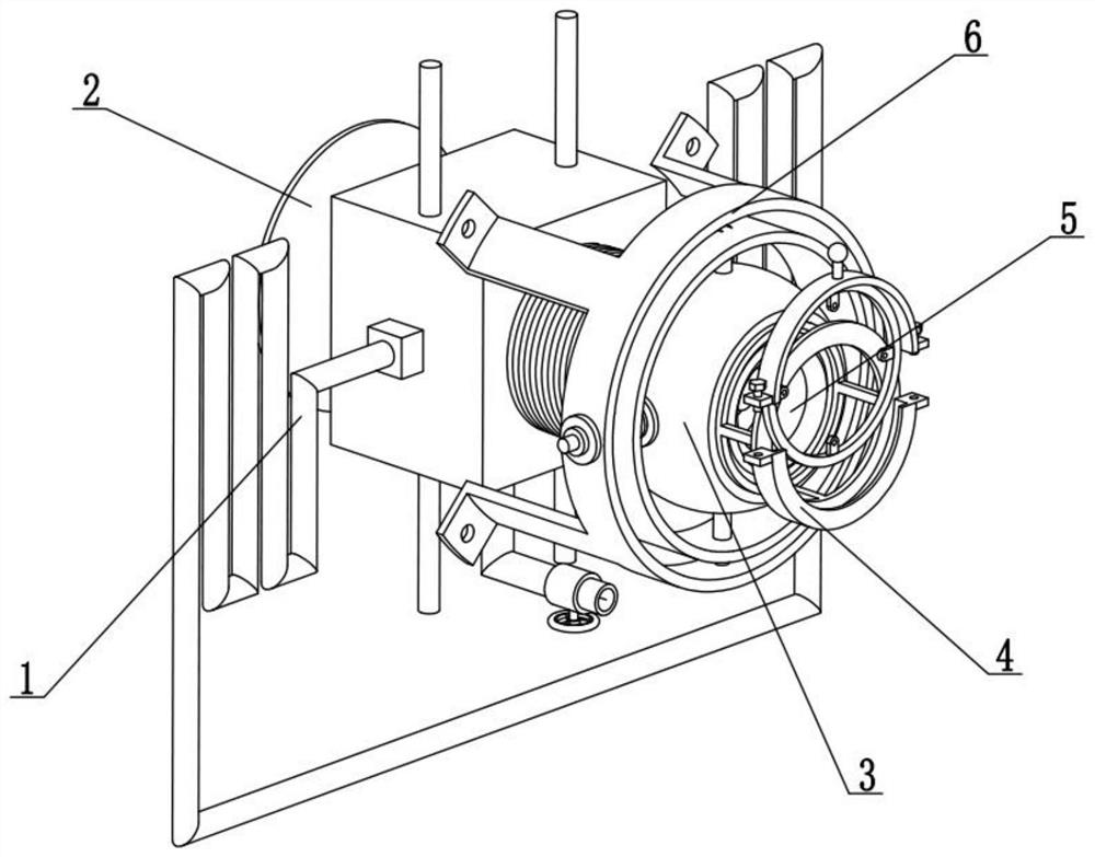
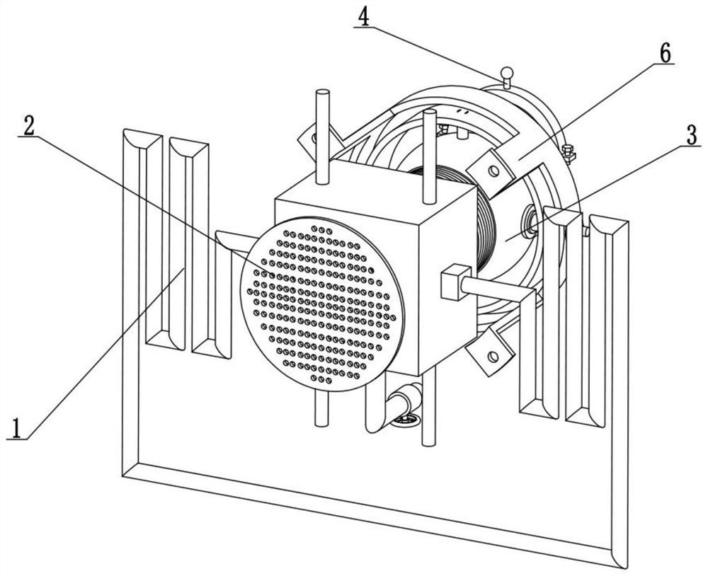
[0026] Combine below Figure 1-9 Describe this embodiment, the present invention relates to the technical field of air-conditioning and cooling, more specifically, an air-conditioning and cooling system based on a building structure, including a circulating refrigeration mechanism 1, an external impurity protection mechanism 2, a cold air delivery mechanism 3, and a cold air dust removal mechanism 4 , the cold air power mechanism 5 and the shaking head adjustment mechanism 6, the external impurity protection mechanism 2 is fixedly connected to the left end of the circulating refrigeration mechanism 1, the left end of the cold air delivery mechanism 3 is fixedly connected to the right end of the circulating refrigeration mechanism 1, and the cold air dust removal mechanism 4 is fixed Connected to the right end of the cold air delivery mechanism 3 , the cold air delivery mechanism 3 is rotatably connected to the shaking head adjustment mechanism 6 , and the cold air power mechani...
specific Embodiment approach 2
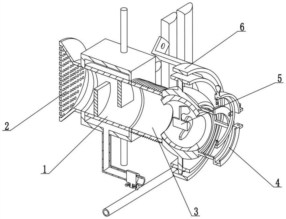
[0029] Combine below Figure 1-9This embodiment will be described. This embodiment will further describe the first embodiment. The circulating refrigeration mechanism 1 includes a cooling circulating water tank 1-1, a wall connecting steel bar 1-2, an air cooling pipe 1-3, and a circulating pressure pump 1- 4. Cooling water running pipes 1-5, water changing pipes 1-6, water changing valves 1-7 and semicircular air deflectors 1-8, multiple semicircular air deflectors 1-8 are evenly spaced At the upper and lower ends of the inner wall of the air cooling pipe 1-3, the air cooling pipe 1-3 is fixedly connected to the cooling circulating water tank 1-1, and the upper and lower ends of the cooling circulating water tank 1-1 are fixedly connected with a plurality of wall connecting steel bars 1 -2, the bottom of the water change pipeline 1-6 is provided with a water change valve 1-7, the top of the water change pipeline 1-6 is fixedly connected to the bottom of the cooling circulatin...
specific Embodiment approach 3
[0032] Combine below Figure 1-9 Describe this embodiment, this embodiment will further explain Embodiment 2. The external impurity protection mechanism 2 includes an air intake flare funnel 2-1 and an impurity blocking net 2-2, and the impurity blocking net 2-2 is fixedly connected to the The left end of the air intake flare funnel 2-1, the right end of the air intake flare funnel 2-1 is fixedly connected to the left end of the air cooling pipe 1-3.
[0033] When the air outside the building enters the air intake flaring funnel 2-1, the impurities in the air will be blocked by the impurity blocking net 2-2, so as to prevent the impurities in the air from entering the interior of the building, and at the same time prevent the impurities in the air from falling on the building-based In the air-conditioning and cooling system with solid structure, it will affect the work.
PUM
 Abstract
Description
Claims
Application Information