Water level monitoring equipment for hydraulic engineering
A technology of water level monitoring and water conservancy engineering, applied in cleaning methods and utensils, displaying liquid level indicators through pressure measurement, cleaning hollow objects, etc., can solve problems such as inability to calculate water pressure
- Summary
- Abstract
- Description
- Claims
- Application Information
AI Technical Summary
Problems solved by technology
Method used
Image

Examples
Embodiment 1
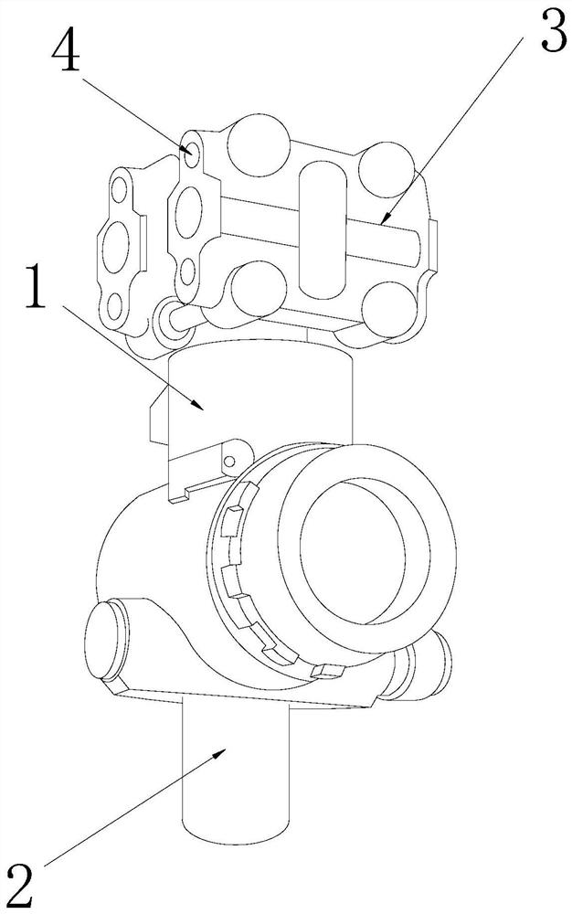
[0025] as attached figure 1 to attach Figure 5 Shown:
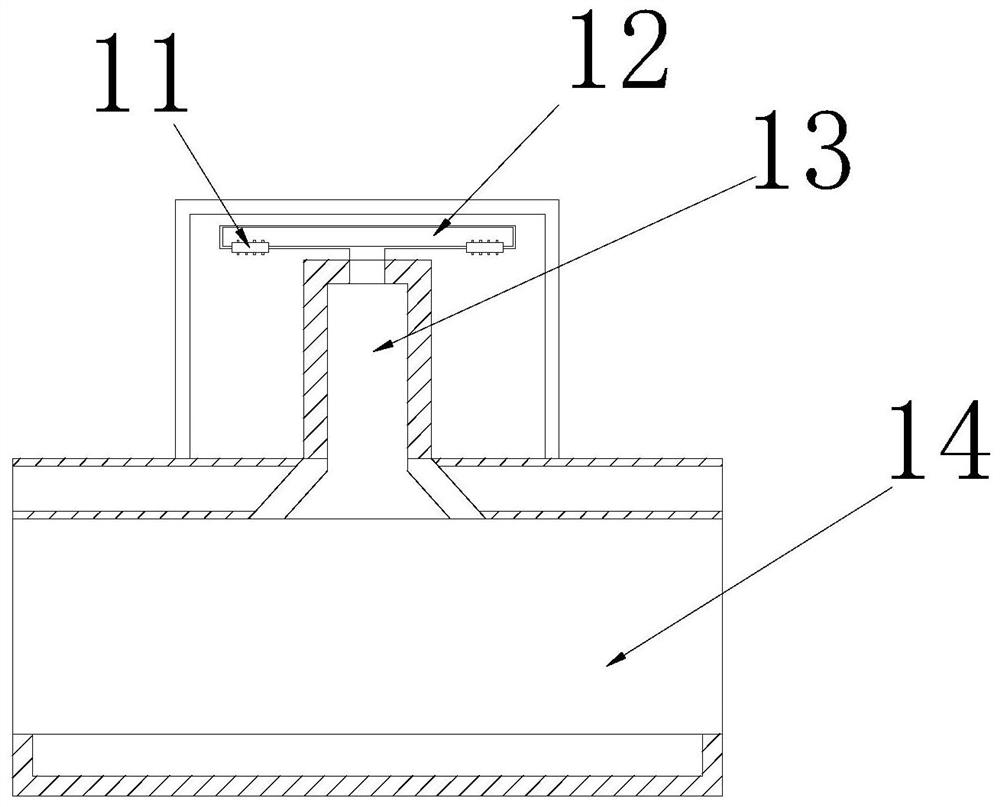
[0026] The invention provides a water level monitoring device for water conservancy projects, the structure of which includes a detection device 1, a fixed column 2, a terminal device 3, and an inlay groove 4. The detection device 1 is embedded and installed directly under the terminal device 3, and the fixed column 2 The flange is connected directly below the detection device 1, the terminal device 3 is located directly above the fixed column 2, and the inlay groove 4 is embedded on the outer end surface of the terminal device 3; the detection device 1 includes a speed ring 11, Circulation pipe 12, pressure pipe 13, and flow pipe 14, the speed ring 11 is inlaid and connected to the inner end surface of the circulation pipe 12, and the circulation pipe 12 is located directly above the pressure pipe 13 and is inlaid and connected to the detection device 1 On the inner wall of the pressure pipe 13, the lower end of the p...
Embodiment 2
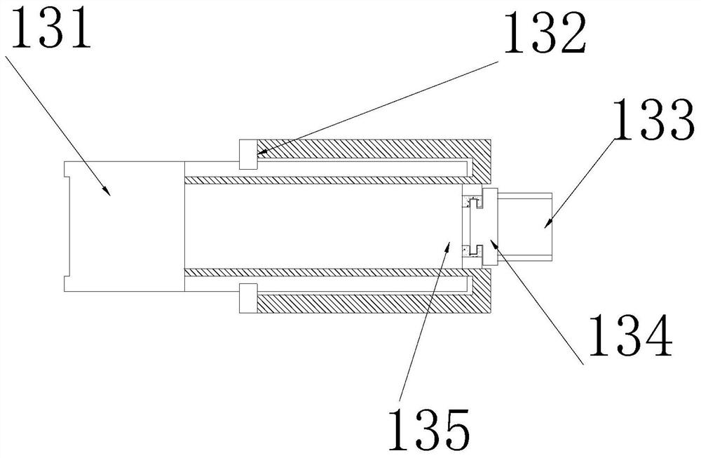
[0032] as attached Figure 5 to attach Figure 7 As shown: the cleaning mechanism 135 includes a cleaning plate 351, a turbulent flow block 352, a guide thread ring 353, and a swash plate 354. The cleaning plate 351 is embedded and attached to the inner upper end surface of the cleaning mechanism 135. Symmetrically installed on the left and right sides of the inner end of the cleaning mechanism 135, the guide thread ring 353 is located directly above the swash plate 354, and the swash plate 354 is symmetrically installed on the left and right sides of the lower end of the turbulent flow block 352, and the turbulent flow block 352 There are through holes through the upper and lower ends, which can effectively change the flow direction of the water flow, so that the water flow collides with each other in the center of the cleaning mechanism 135, forming turbulent flow to impact the sediment attached to the surface.
[0033] Wherein, the cleaning disk 351 includes a guide groove...
PUM
 Abstract
Description
Claims
Application Information
 - R&D
- Intellectual Property
- Life Sciences
- Materials
- Tech Scout
- Unparalleled Data Quality
- Higher Quality Content
- 60% Fewer Hallucinations
Browse by: Latest US Patents, China's latest patents, Technical Efficacy Thesaurus, Application Domain, Technology Topic, Popular Technical Reports.
© 2025 PatSnap. All rights reserved.Legal|Privacy policy|Modern Slavery Act Transparency Statement|Sitemap|About US| Contact US: help@patsnap.com