Magnetic force loading device and loading method

A technology of loading device and magnetic force, applied in measuring device, using stable tension/pressure test material strength, instrument, etc., can solve the problem of inability to load, unsatisfactory force load simulation effect, and difficult to achieve the distribution density of loading points, etc. problem, to achieve the effect of easy replacement

Active Publication Date: 2020-11-06
BEIJING RES INST OF MECHANICAL & ELECTRICAL TECH
View PDF8 Cites 0 Cited by
  • Summary
  • Abstract
  • Description
  • Claims
  • Application Information

AI Technical Summary

Problems solved by technology

Traditional static loading methods usually use mechanical static loading system or electro-hydraulic servo loading system to realize single-point or multi-point concentrated force loading. If the distribution density of loading points is high, the degree of approximation to continuous distribution is also high. However, , in view of the large space requirements of the mechanical loading system itself, it is difficult to achieve an excessively high distribution density of loading points, so the simulation effect of continuously distributed force loads is not satisfactory
With the development of composite materials, aircraft and spacecraft often use composite materials. For composite material test pieces, they cannot bear concentrated loads, and cannot be loaded by punching holes and destroying the surface of test pieces.

Method used


Image

  • Magnetic force loading device and loading method
  • Magnetic force loading device and loading method
  • Magnetic force loading device and loading method

Examples


Embodiment 1

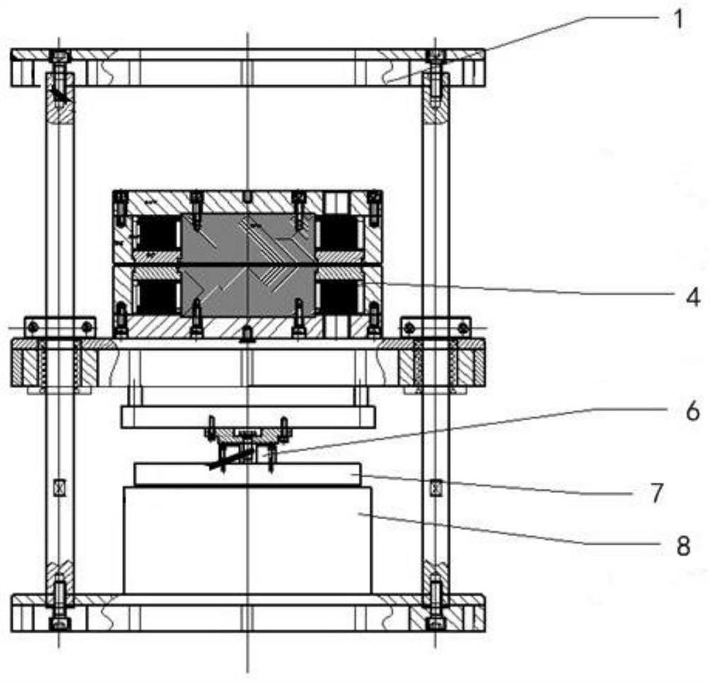
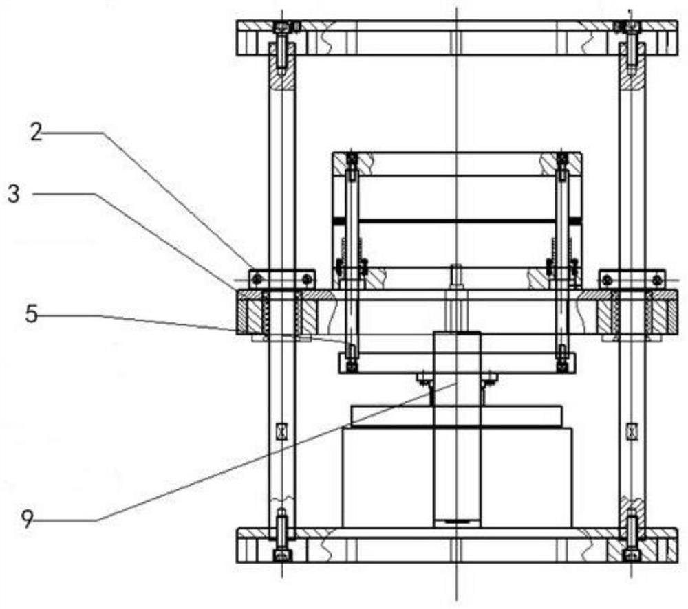
[0041] One embodiment of the present invention, magnetic loading device and loading method, such as Figure 1 to Figure 6 As shown, the magnetic loading device includes a mounting bracket 1 , a lifting platform 3 , a loading system 4 , a connecting guide device 5 , a tooling 7 , a test piece platform 8 and a lifting device 9 .

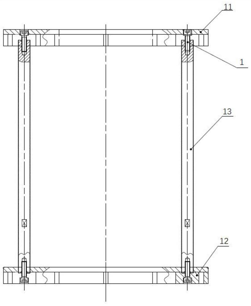
[0042] The mounting bracket 1 includes an upper plate 11, a lower plate 12 and a column 13. The mounting bracket 1 provides support for the magnetic force loading device, fixes the entire magnetic force loading device, carries the suction force between the electromagnets during the test, and serves as a motion guide for the lifting platform 3 , to facilitate the up and down movement of the lifting platform 3. Exemplarily, the upper plate 11 and the lower plate 12 are square plates. The lower plate 12 provides support for the entire magnetic loading device, and at the same time, the lower plate 12 provides an installation platform for the test piece pl...

Embodiment 2

[0062] In order to further verify the magnetic loading device of this embodiment, a verification test of the magnetic loading device was carried out for a C / SiC test piece with a size of 400×400×3 mm, and the force value and voltage and current data were recorded and analyzed. Specific steps include:

[0063] Step 1. Raise the lifting platform and install the test piece:

[0064] Loosen the locking screw of the locking device 2, and inflate the cylinder of the lifting device 9 through the three-dimensional five-way valve, so that the cylinder drives the lifting platform 3 and the loading system 4 on the lifting platform 3 to slowly rise along the column 13 of the mounting bracket 1 to The highest position, and then put a 400×400×3mm C / SiC test piece on the test piece platform 8 .

[0065] Step 2. Fixed loading system:

[0066] The cylinder of the lifting device 9 is deflated through the three-dimensional five-way valve, so that the cylinder drives the lifting platform 3 and ...


PUM


Abstract

The invention relates to a magnetic force loading device and a magnetic force loading method, which belong to the technical field of static tests and solve the problems that an existing mechanical loading system is difficult to simulate continuously distributed force loads, and a test piece is damaged in the loading process. The magnetic force loading device comprises a lifting platform, a loadingsystem, a connection guide device, a tool and a test piece platform, the loading system is connected with the connecting guide device and is arranged on the lifting platform; the tool is arranged atthe lower part of the lifting platform and is connected with the lower part of the connection guide device; the loading system generates magnetic force after being powered on and can drive the tool tomove downwards to apply load to the test piece placed on the test piece platform. According to the invention, attraction force is generated between the upper electromagnet and the lower electromagnet, and uniformly distributed loads can be provided for the test piece under the condition of not damaging the test piece.

Description

technical field [0001] The invention relates to the technical field of static test, in particular to a load application method of a test piece in the static test. Background technique [0002] For static test loading, it is difficult to realize the continuous distribution of force load. Traditional static loading methods usually use mechanical static loading system or electro-hydraulic servo loading system to realize single-point or multi-point concentrated force loading. If the distribution density of loading points is high, the degree of approximation to continuous distribution is also high. However, , in view of the large space requirements of the mechanical loading system itself, it is difficult to achieve a high distribution density of loading points, so the simulation effect of the continuous distribution of force load is not satisfactory. With the development of composite materials, composite materials are often used in aircraft and spacecraft. For composite material...

Claims


Application Information

Patent Timeline
Patent Type & Authority Applications(China)
IPC IPC(8): G01N3/08G01N3/02
CPCG01N3/08G01N3/02G01N2203/005
Inventor 孟祥男严超魏冉
Owner BEIJING RES INST OF MECHANICAL & ELECTRICAL TECH
Why Eureka
Try Eureka