
Light emitting device and projection system

A technology for a light-emitting device and an excitation light source, applied in the field of lighting, can solve the problems of difficulty in achieving high efficiency, inconvenient heat dissipation of wavelength conversion materials, and uneven distribution of excitation light intensity.

Active Publication Date: 2020-11-06
WUXI SEEMILE LASER DISPLAY TECH
View PDF6 Cites 4 Cited by
  • Summary
  • Abstract
  • Description
  • Claims
  • Application Information

AI Technical Summary

Problems solved by technology

Taking green light as an example, the current green LED or green laser is difficult to achieve high efficiency and the price is very high; while the solid-state devices of blue light and UV light have high efficiency and low price, it is no doubt that the latter scheme is used to generate green light. Has a bigger market prospect
[0004] In current light-emitting devices based on wavelength conversion methods, the intensity distribution of the excitation light is not uniform enough, making the excitation efficiency of the wavelength conversion material low; in addition, the existing light-emitting devices usually use focusing lenses to collect the excited light generated by the wavelength conversion material ( Chromatic light), so that the collection efficiency of the excited light is low; at the same time, the focusing lens is close to the wavelength conversion device, which causes the heat dissipation of the wavelength conversion material to be inconvenient, and affects the excitation efficiency of the wavelength conversion material
Since the excitation efficiency of the wavelength conversion material directly affects the luminous efficiency of the light-emitting device, the luminous efficiency of the existing light-emitting device is relatively low

Method used


Image

  • Light emitting device and projection system
  • Light emitting device and projection system
  • Light emitting device and projection system

Examples


Embodiment Construction

[0026] The technical solutions of the present invention will be clearly and completely described below in conjunction with the embodiments. Obviously, the described embodiments are part of the embodiments of the present invention, but not all of them. Based on the embodiments of the present invention, all other embodiments obtained by persons of ordinary skill in the art without making creative efforts belong to the protection scope of the present invention.

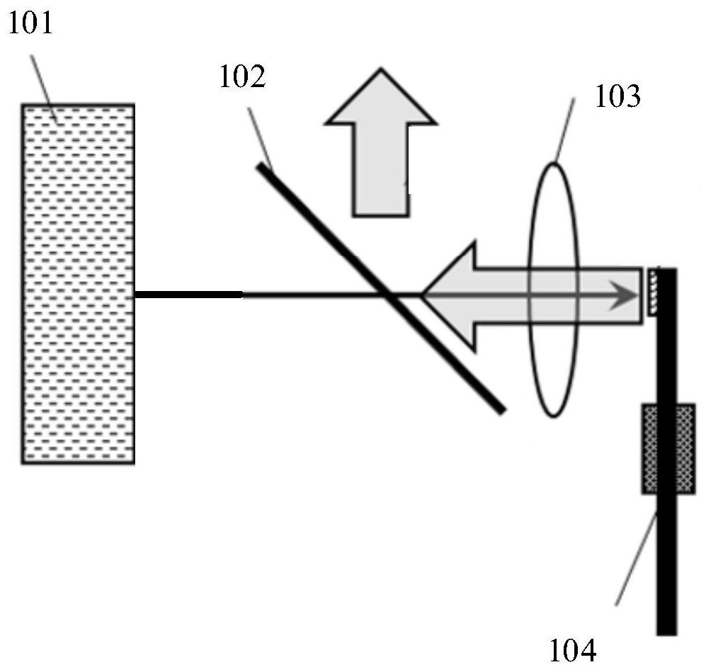
[0027] see figure 1 Shown is a schematic structural diagram of a light emitting device in the prior art. The existing light emitting device generally includes an excitation light source 101, a dichroic mirror 102, a focusing lens 103 and a wavelength conversion device 104, and the wavelength conversion device 104 is provided with a wavelength conversion material . The excitation light emitted by the excitation light source 101 passes through the dichroic mirror 102, and then focuses on the wavelength conversion device 1...


PUM


Abstract

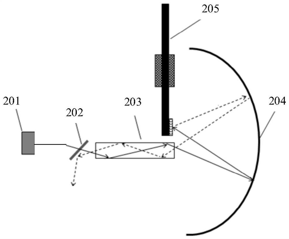
The invention provides a light emitting device and a projection system, which relate to the technical field of lighting. The light emitting device comprises an excitation light source, a dichroscope,a dodging element, a cambered surface reflection element and a wavelength conversion device. The excitation light source is located on one side of the dichroscope, the cambered surface reflection element is located on the other side of the dichroscope, the dodging element is arranged between the dichroscope and the cambered surface reflection element, and the wavelength conversion device and the dodging element are located on the same side of the cambered surface reflection element. The cambered surface reflection element is ellipsoidal, and the end face center point of the end, away from thedichroscope, of the dodging element and the wavelength conversion point of the wavelength conversion device are located at the two focuses of the cambered surface reflection element respectively. According to the light emitting device and the projection system provided by the invention, through the dodging element and the cambered surface reflection element, the dodging effect of the exciting light incident on the wavelength conversion material is improved, the heat dissipation space of the wavelength conversion device is increased, and the collection efficiency of the excited light is improved, so that the light emitting efficiency is improved.

Description

technical field [0001] The invention relates to the technical field of lighting, in particular to a light emitting device and a projection system. Background technique [0002] Traditional light sources such as fluorescent lamps, incandescent lamps, ultra-high performance lamps or xenon lamps are difficult to achieve high efficiency and long life. With the development of solid-state light sources, LEDs (Light Emitting Diodes, light-emitting diodes) and semiconductor lasers have gradually entered the lighting and display markets. [0003] There are generally two ways to produce colored light or white light: one is to directly use colored light sources such as red, green or blue LEDs to provide colored light, or use these colored lights to synthesize white light; the other is to use excitation light sources to excite based on light wavelength conversion. The wavelength conversion material produces colored light, for example, a light source with a short wavelength such as blue...

Claims


Application Information

Patent Timeline
Patent Type & Authority Applications(China)
IPC IPC(8): G03B21/20G02B27/09
CPCG02B27/0938G02B27/0955G03B21/204G03B21/2066G03B21/208
Inventor 葛明星陈龙
Owner WUXI SEEMILE LASER DISPLAY TECH
Learn More